
Page 617 - Industrial Power Engineering and Applications Handbook
P. 617
17/582 Industrial Power Engineering and Applications Handbook
T Protective BIL of motor Protective
(' Interrupter level margin
P ~- available
For a lightning 17.7 kV 31 kV 175% ... OK
Transformer impulse wave of
5 kA (8120 ps)
~~
( 9 Interrupter
For a switching 15.3 kV [governed by OK
- - - impulse wave of 21.5 kV the lightning Not suitable
1 .O kA (30/60 ps)
impulse]
T
CS 1 (i_ T;'k normal design 125% :. OK
16.2 kV for
For a FOW
(1/2 ps) of 10 kA
26.9 kV for
special design
The distribution system may be considered as solidly grounded
having a GFF' of 1.4 and devoid of any other TOVs.+
Therefore, maximum rated voltage = 1.4 x 4.2
00 = 5.88 kV
M Select the nearest voltage rating of a station class surge
arrester (see also Section 18.8) from the manufacturer's
,G catalogue, (Table 18.8) as 6 kV which has the following
protective levels:
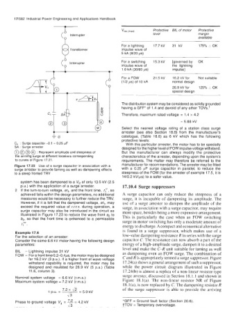
C, : Surge capacitor -0.1 - 0.25 pF With this particular arrester, the motor has to be specially
SA : Surge arrester designed for the higher level of FOW impulse voltage withstand.
@ @ @ @ : Represent amplitude and steepness of But the manufacturer can always modify the protective
the arriving surge at different locations corresponding characteristics of the arrester, depending upon the system's
to curves of Figure 17.21. requirements. The matter may therefore be referred to the
Figure 17.23 Use of a surge capacitor in association with a manufacturer for recommendations. The arrester may be fitted
surge arrester to provide taming as well as dampening effects with a 0.25 pF surge capacitor in parallel, to reduce the
to a steep fronted TRV steepness of the FOW (for the arrester of example 17.5, it is
14/0.2 kVlps) to a safer value.
system has been dampened to a V,, of only 13.5 kV (2.5
P.u.) with the application of a surge arrester. 17.10.4 Surge suppressors
2 If the turn-to-turn voltage, et,, and the front time, fy, so
achieved falls within the design parameters, no additional A surge capacitor can only reduce the steepness of a
measures would be necessary to further reduce the TRV. surge, it is incapable of dampening its amplitude. The
However, if it is felt that the dampened voltage, et,, may use of a surge arrester to dampen the amplitude of the
exceed the required value of r.r.r.v. during operation, a surge, in association with a surge capacitor, may require
surge capacitor may also be introduced in the circuit as more space, besides being a more expensive arrangement.
illustrated in Figure 17.23 to reduce the wave front a? to This is particularly the case when an FOW switching
b,, so that the front time is enhanced to a permissible surge in motor switching has only a moderate amount of
t;'.
energy to discharge. A compact and economical alternative
is found in a surge suppressor, which makes use of a
Example 17.6
For the selection of an arrester: low-value dampening resistance R in series with the surge
Consider the same 6.6 kV motor having the following design capacitor C. The resistance can now absorb a part of the
parameters: energy of a high-amplitude surge, dampen it to a desired
level and make the C-R unit suitable for taming as well
BIL - Lightning impulse 31 kV as dampening even an FOW surge. The combination of
FOW - For a front time 0.2-0.4ps, the motor may be designed C and R is appropriately termed a surge suppressor. Figure
for 16.2 kV (3 P.u.). If a higher front of wave voltage
withstand capability is required, the motor may be 17.24(a) shows a general arrangement of such a suppressor,
designed and insulated for 26.9 kV (5 P.u.) (Table while the power circuit diagram illustrated in Figure
11.6, column 3). 17.24(b) is almost a replica of a non-linear resistor type
Nominal system voltage = 6.6 kV (rms.) surge arrester, discussed in Section 18.1.1 and shown in
Maximum system voltage = 7:2 kV (rms.) Figure 18.1(a). The non-linear resistor NR of Figure
18.1 (a), is now replaced by C. The dampening resistor R
7.2 x &
1 D.U. = - of the surge suppressor is able to provide the arriving
=
5.9
kV
43
Phase to ground voltage V, = = 4.2 kV *GFF = Ground fault factor (Section 20.6).
1/3 tTOV = Temporary overvoltage.