
Page 613 - Industrial Power Engineering and Applications Handbook
P. 613
17/578 Industrial Power Engineering and Applications Handbook
as a power station or a process plant, to avoid the least Test results
risk. In our discussion so far, the circuit conditions, as
assumed and the analysis of the voltage surges as The test circuit may be connected to the test voltage and
generated, were purely statistical and varied from machine then switched to obtain the required oscillograms during
to machine and from one installation to another. The switching operations and assess the following:
purpose so far has been to provide a general analysis of
surge voltage phenomenon, its consequences on the Any restrikes and their number
machine and possible remedies and/or protection. For Amplitude of voltage surge (V,) generated and
absolute motor protection, accurate transient conditions Their rise time (t,).
must be known. To determine the transient conditions
accurately, a working committee of the IEEE-Cigre has With these data, one can determine the dielectric curve
suggested a simulated test circuit (Electra, 198 I; Gibbs the machine must have when switched with such an
et al., 1989) for all manufacturers of interrupting devices interrupting device. This can be compared with the actual
(1) to determine the behaviour of their devices, with dielectric curve of the machine (Figure 17.18) obtained
predetermined circuit parameters, almost representing a from its manufacturer to decide the compatibility of the
normal supply side of the machine; (2) to assess the interrupting device for the machine or vice versa and the
behaviour of the machine during a switching operation extent of surge protection, if necessary. For more details
and subsequent restrikes, if any, as a guideline for the and results of similar simulation tests, see Central Board
user; and (3) to decide on the more appropriate switching of Irrigation and Power (1 995).
device for the machine and its surge protection, based on
the dielectric capability of the machine (Figure 17.18).
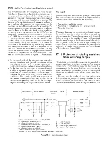
The test circuit is illustrated in Figure 17.19 simulating: 17.1 0 Protection of rotating machines
from switching surges
On the supply side of the interrupter, an equivalent
busbar, inductance and lumped capacitance with a For adequate protection of the machine it is essential to
provision to connect p.f. correction capacitors, if know the amplitude, V,, and the rise time, tl of the severest
required, to represent a replica of the actual installation. voltage surge (FOW) that may occur on the system. It is
On the load side, the interrupter is connected through recommended that the actual field tests be conducted for
a cable to the equivalent circuit, with the required large installations according to the recommended
quantities of lumped resistance and reactance, to simulation test circuits, noted above, to ascertain these
represent the motor to be tested, under a locked rotor surges.
condition. The circuit would also represent an The tests may be conducted on a few ratings with
interruption immediately after a start, to check for the different sizes and lengths of cables to simulate the near
most onerous operating condition for the interrupter actual condition of the installation. One should be more
to generate the highest surges as discussed earlier. conservative than liberal on cable lengths to obtain safe
I I I 1 I
' Supply source ' Busbar section Test circuit Cable ~ Motor substitute
1 1 breaker I
8 ,
I I I 1 I
L R
Typical parameters as recommended by ClGRE
2, = Grounding impedance = 5 Q L = Load inductance
L, = Source inductance = 4 mH R = Load resistance
C, = Compensation capacitance = 0.0 or 7.0 pF C, = Load parallel capacitance
C, = Busbar capacitance = 40 nF Rp = Load parallel resistance
L, = Busbar inductance = 25 pH
Cable = 100 m screened, radial field 3 X
Unipolar Z, = 40 a, 95 mmZ AI unrolled and grounded at both ends.
Figure 17.19 A simulated test circuit