
Page 608 - Industrial Power Engineering and Applications Handbook
P. 608
Voltage surges-causes, effects and remedies 17/573
such as an induction motor’s winding, most of its stress If we consider some length of the interconnecting cables
may appear only across a small part of the windings (the and deduct this from the total length of 20 m. the interturn
line end coil or the first coil). The front of the surge will stresses may assume much more dangerous proportions.
become less steep as it penetrates the windings, due to The interturn insulation of the windings must be suitable
lumped capacitances C of the winding insulation and to withstand even a higher impulse level than calculated
also because of partial reflections and damped refractions above. As standard practice, the whole coil, if it is pre-
(Section 18.5.1) from the discontinuities of the windings formed, is tested for the prescribed impulse withstand
as well as eddy currents (Section I .6.2.A-iv) which will level as in Table 11.6. It should be ensured that thc actual
add to ‘L’. The interturn voltage stress will thus be higher steepness and amplitude of the FOW is well within the
for the line end coil of the windings than the subsequent prescribed BIL.
coils as shown by the following example. The first few turns of the line end coil of a motor or
transformer and short lengths of interconnecting cables
Example 17.1 and overhead lines and their associated terminal
A simple switching surge of, say, 250/2500 ps (Sections 17.3.1 equipment, will thus be subject to severe stresses and
and 17.6.6 for velocity) would mean that in free space, will be rendered vulnerable to damage by such steep-
considering the speed of propagation as 200 m/p, it will fronted tranbient voltages.
propagate by Various experiments conducted by different agencies
have revealed that the voltage stress across the first coil
250 x 200 x lo6 = 50 km alone may be as high as 70-904 of the total transient
106 1000
voltage acr05b a motor windings, having a front time. t,
by the time it reaches its first peak. Considering an average as low as 0.2 ,us. (see Working Group 13.02 of Study
velocity of propagation in windings inside the slots and Committee 13 (1981) and Slamecka (1983)).
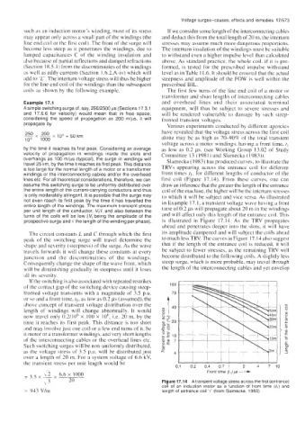
overhangs as 100 m/ps (typical), the surge in windings will Slamecka ( 1983) has produced curves. to illustrate the
travel 25 km, by the time it reaches its first peak. This distance
is too large for the normal length of a motor or a transformer TRVs appearing across the entrance coil for different
windings or the interconnecting cables and/or the overhead front times t,, for different lengths of conductor of the
lines etc. For all theoretical considerations, therefore, we can first coil (Figure 17.14). From these curves, one can
assume this switching surge to be uniformly distributed over draw an inference that the greater the length of the entrance
the entire length of the current-carrying conductors and thus coil of the machine, the higher will be the intcrturn stresses
is only moderately stringent. It is possible that the surge may to which it will be subject and vice versa. As illustrated
not even reach its first peak by the time it has travelled the in Example 17. I, a transient voltage wave having a front
entire length of the windings. The maximum transient stress
per unit length of the conductor, %/I, and also between the time of 0.2 ps will propagate about 20 m in the windings
turns of the coils will be low (V, being the amplitude of the and will affect only this length of the entrance coil. This
prospective surge and Y the length of the winding per phase). is illustrated in Figure 17.14. As the TRV propagates
ahead and penetrates deeper into the slots, it will have
The circuit constants L and C through which the first its amplitude dampened and will subject the coils ahead
peak of the switching surge will travel determine the to much less TRV. The curves in Figure 17.14 also suggest
shape and severity (steepness) of the surge. As the wave that if the length of the entrance coil is reduced, it will
travels forwards it will change these constants at every be subject to fewer stresses, as the remaining TRV will
junction and the discontinuities of the windings. become distributed to the following coils. A slightly less
Consequently change the shape of the wave front, which steep surge, which is more probable, may travel through
will be diminishing gradually in steepness until it loses the length of the interconnecting cables and yet envelop
all its severity.
If the switching is also associated with repeated restrikes
of the contact gap of the switching device causing steep-
fronted voltage transients with a magnitude of 3.5 p.u.
or so and a front time, r,. as low as 0.2 ps (assumed), the
ahove concept of transient voltage distribution over the -
-
length of windings will change abnormally. It would 8
a,
now travel only 0.2/106 x 100 x IO6, i.e. 20 m, by the c
m
time it reaches its first peak. This distance is too short c
c
a,
and may involve just one coil or a few end turns of it, be >al
f
it motor or a transformer windings, and very short lengths -
of the interconnecting cables or the overhead lines etc. 0
m
Such switching surges will be non-uniformly distributed, 6
as the voltage stress of 3.5 p.u. will be distributed just _J
a,
over a length of 20 m. For a system voltage of 6.6 kV,
the transient stress per unit length would be
01 02 04 07 1 2 4 7 10
Front time (t,) ps -----c
Figure 17.14 A transient voltage stress across the first (entrance)
coil of an induction motor as a function of front time (t,) and
913 V/m length of entrance coil ’(’ (from Slamecka, 1983)