
Page 607 - Industrial Power Engineering and Applications Handbook
P. 607
17/572 Industrial Power Engineering and Applications Handbook
Leaf springs
Movinq
Fixed
contacts
COll mounted on
the moving
contacts
Spring-loaded moving contact assembly
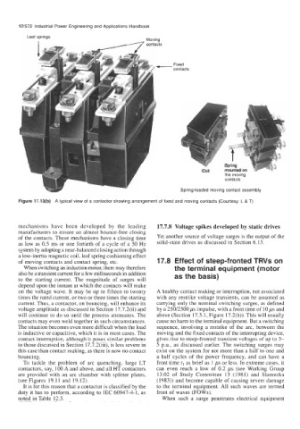
Figure 17.13(b) A typical view of a contactor showing arrangement of fixed and moving contacts (Courtesy: L & T)
mechanisms have been developed by the leading 17.7.8 Voltage spikes developed by static drives
manufacturers to ensure an almost bounce-free closing
of the contacts. These mechanisms have a closing time Yet another source of voltage surges is the output of the
as low as 0.5 ms or one fortieth of a cycle of a 50 Hz solid-state drives as discussed in Section 6.13.
system by adopting a near-balanced closing action through
a low-inertia magnetic coil, leaf spring cushioning effect
of moving contacts and contact spring, etc. 17.8 Effect of steep-fronted TRVs on
When switching an induction motor, there may therefore the terminal equipment (motor
also be a transient current for a few milliseconds in addition
to the starting current. The magnitude of surges will as the basis)
depend upon the instant at which the contacts will make
on the voltage wave. It may be up to fifteen to twenty A healthy contact making or interruption, not associated
times the rated current, or two or three times the starting with any restrike voltage transients, can be assumed as
current. Thus, a contactor, on bouncing, will enhance its carrying only the nominal switching surges, as defined
voltage amplitude as discussed in Section 17.7.2(ii) and by a 250/2500 ps impulse, with a front time of 10 ps and
will continue to do so until the process attenuates. The above (Section 17.3.1, Figure 17.2(b)). This will usually
contacts may even weld together in such circumstances. cause no harm to the terminal equipment. But a switching
The situation becomes even more difficult when the load sequence, involving a restrike of the arc, between the
is inductive or capacitive, which it is in most cases. The moving and the fixed contacts of the interrupting device,
contact interruption, although it poses similar problems gives rise to steep-fronted transient voltages of up to 3-
to those discussed in Section 17.7.2(iii), is less severe in 5 P.u., as discussed earlier. The switching surges may
this case than contact making, as there is now no contact exist on the system for not more than a half to one and
bouncing. a half cycles of the power frequency, and can have a
To tackle the problem of arc quenching, large LT front time tl as brief as 1 ps or less. In extreme cases, it
contactors, say, 100 A and above, and all HT contactors can even reach a low of 0.2 ps (see Working Group
are provided with an arc chamber with splitter plates, 13.02 of Study Committee 13 (1981) and Slamecka
(see Figures 19.11 and 19.12). (1983)) and become capable of causing severe damage
It is for this reason that a contactor is classified by the to the terminal equipment. All such waves are termed
duty it has to perform, according to IEC 60947-4-1, as front of waves (FOWs).
noted in Table 12.5. When such a surge penetrates electrical equipment