
Page 612 - Industrial Power Engineering and Applications Handbook
P. 612
Voltage surges-causes, effects and remedies 17/577
0 The lower ratings of rotating machines, having full ClGRE envelope
load current of around 60 A and less, i.e. 600 kW (based on the data obtained from
or less for a 6.6 kV system and 300 kW or less for a few manufacturers on a new winding)
a 3.3 kV system, are generally prone to cause /
dangerous steep-fronted TRVs when being inter-
rupted on no-load by a VCB or a vacuum contactor,
as a result of possible current chopping. For a full
load current of 60 A, the no-load current would be
approximately 50%, i.e. 30 A or even less (Section
1.7). It is therefore possible that current chopping
may take place just before a natural current zero at
around 10% if it, i.e. 3 A or so. Refer to Figure
17.17. The latest vacuum interrupters with Cu-Cr
alloy contacts (Section 19.5.6) may not allow the
current to reach its natural zero for a normal
interruption and may chop it somewhere near 3-5
A and cause TRVs. Moreover, the lowest rating of 0 1 Front time (t,) ps - 6
4
5
3
2
the interrupting device itself may be large enough
for this current to be interrupted at current zero and
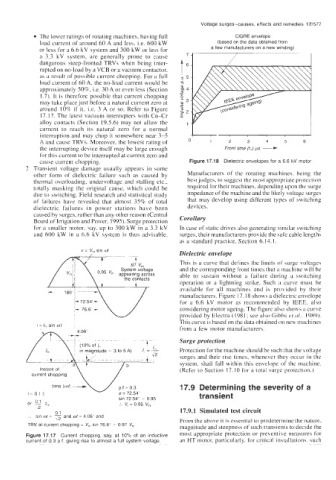
cause current chopping. Figure 17.18 Dielectric envelopes for a 6.6 kV motor
2 Transient voltage damage usually appears in some
other form of dielectric failure such as caused by Manufacturers of the rotating machines. being the
thermal overloading, undervoltage and stalling etc., best judges, to suggest the most appropriate protection
totally masking the original cause, which could be required for their machines, depending upon the surge
due to switching. Field research and statistical study impedance of the machine and the likely voltage surges
of failures have revealed that almost 35% of total that may develop using different types of switching
dielectric failures in power stations have been devices.
caused by surges, rather than any other reason (Central
Board of Irrigation and Power, 1995). Surge protection Corollary
for a smaller motor, say, up to 300 kW in a 3.3 kV In case of static drives also generating similar switching
and 600 kW in a 6.6 kV system is thus advisable. surges, their manufacturers provide the safe cable lengths
as a standard practice, Section 6.14.1.
v = V, sin wt
Dielectric envelope
This is a curve that defines the limits of surge voltages
and the corresponding front times that a machine will be
0 95 vm appearing across able to sustain without a failure during a switching
the contacts
operation or a lightning strike. Such a curve must be
available for all machines and is provided by their
manufacturers. Figure 17. I8 shows a dielectric envelope
for a 6.6 kV motor as recommended by IEEE, also
considering motor ageing. The figure also shows a curve
provided by Electra (1981; see also Gibbs et (11.. 1989).
This curve is based on the data obtained on new machines
from a few motor manufacturers.
Surge protection
Protection for the machine should be such that the voltage
surges and their rise times, whenever they occur in the
system, shall fall within this envelope of the machine.
V
current chopping (Refer- to Section 17.10 for a total surge protection.)
time (of) p.f = 0.3 17.9 Determining the severity of a
i=O1 I, i$ = 72.54' transient
sin 72 54" = 0.95
or K! I, :. V, = 0.95 V,,,
\2 17.9.1 Simulated test circuit
0.1
:. sin ot = - and wf = 4.06' and
1'2 From the above it is essential to predetermine the nature.
TRV at current chopping = V, sin 76.6" 0.97 V, magnitude and steepness of such transients to decide the
Figure 17.17 Current chopping, say, at 10% of an inductive most appropriate protection or preventive measures for
current of 0.3 p.f. giving rise to almost a full system voltage. an HT motor, particularly. for critical installations. such