
Page 609 - Industrial Power Engineering and Applications Handbook
P. 609
17/574 Industrial Power Engineering and Applications Handbook
the whole windings. It has been observed that TRVs desirable. It is possible to modify the Z, of a machine at
with a front time of 0.5 ,us and more are fairly evenly the design stage to contain the prospective voltage, V,,
distributed over the entire length of windings. within safe limits if the type of interrupter, length of
Different installations with different lengths of interconnecting cables and the characteristics of the likely
interconnecting cables, type of switching device, size prospective surges are known.
and design parameters of a machine (particularly a rotating
machine), will influence the steepness of surges and their Note
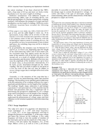
distribution over the length of windings. Different studies The length of the interconnecting cables plays a vital role in containing
at different locations have revealed the following or enhancing the severity of the incidence wave. After the interrupter,
information: the surge enters the cable and propagates ahead. As it propagates,
it rises in amplitude, at a rate of Vt/t, (Figure 17.15) until it reaches
the far end of the cable. The longer the cable, the higher will
If the surge is very steep, say, with a front time of 0.2 become the amplitude of the incidence wave which will be more
ps or less, and the cable length is short, say, 10 m severe for the terminal equipment (refer to protective distances,
(presumed), it may inflict all its severity to only the Section 18.6.2). The length of the interconnecting cable is therefore
entrance coil of the machine and sometimes even only recommended to be as short as possible. The manufacturer of the
a few entrance turns of this coil. However, with the interrupting device can suggest a safe length for different sizes of
cables, depending upon the voltage of the system and the equipment
technological improve-ment of switching devices, the it is feeding.
arc prestrikes are now less predominant or non-existent The approximate values of the surge impedances of motors and
and hence, the switching surge may not be as steep as transformers of various ratings and voltages may be obtained from
described here. their manufacturers and drawn in the form of a graph, as in Figure
In all probability the steepness may be between 0.2 17.7. With the help of these values, one can determine the likely
and 0.4 ,us, in which case, depending upon the length surge voltage from the graphs of Figure 17.8 that may develop
of the interconnecting cables and of each motor coil, when using different interrupting devices.
To this value is added thc peak phase voltage of 1 P.u., of the
the maximum surge may appear across the last few system to determine the total peak voltage likely to arise on a no-
turns of the entrance coil or the first few turns of the load interruption. This total peak voltage should be less than the
second coil, as a result of multiple reflections at the impulse voltage withstand level of the equipment. For motors, it
discontinuities and the joints. Multiple reflections may should be well within the impulse test values given in Table 11.6.
raise the amplitude of the incidence wave up to twice lhe effect of cable length is ignored, presuming that the cable
its initial value, as discussed later. Alternatively, if it length is short and does not contribute in enhancing the severity of
be fairly evenly distributed through-out the whole the incidence wave.
winding. The last coil where it makes its star point or
a few last turns of this last coil may be subject to Example 17.2
Consider a 500 hp (e 500 kVA) 6.6 kV motor. The surge
severe voltage surges due to multiple reflections at the impedance from Figure 17.7(b) Z, = 4500 R. This surge
star point. impedance may generate the following surge voltages during
an interruption by different interrupting devices, depending
upon their chopping currents, according to Figure 17.8:
Generally, it is the steepness of the surge that has a
greater severity on interconnecting cables and machine
windings. The travelling waves and their partial reflections
at the discontinuities of the windings influence the surge’s
amplitude and distribution over the length of the windings.
The windings’ length, shape, inductance L and leakage
capacitance C and speed and size of the machine may be
termed vital parameters that play a significant role in
determining the prospective amplitude (V,) of a voltage
surge and its distribution over the length of the windings.
Below, we briefly discuss such parameters to better t, > r;’ > r;
understand the phenomenon of voltage surges and their v, > v,- z v,.
influence on the terminal equipment and interconnecting Longer the cable,
cables. higher will be ‘t’ and
more severe will
become the ‘TRV’
17.8.1 Surge impedance
The value of L and C of a machine will determine its
surge impedance Z, = and surge frequency
f, = 1/(27cTm). A low surge impedance will help to
dampen the prospective amplitude, V,, of the surge voltage
and hence the stresses on the windings. A low surge
frequency will help to limit the number of restrikes of tl Rise time (t) -
the interrupter and in turn the amplitude of the surge, VV
A lowerf, will also reduce the steepness, V,/t,, of the
surge. Hence, a low Z, as well as a lowf, are always Figure 17.15 Influence of cable length on the TRV