
Page 760 - Industrial Power Engineering and Applications Handbook
P. 760
R,, = ground resistance of power plant area
R,, = ground resistance of switchyard area
R,, = total ground resistance of power plant
and twitchyard areas in parallel
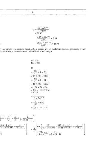
5 Fault current sharing by the two ground mats kA I = 40 x0.0477 40 x 0.0477
g' 0.103 I,2 = 0.089
= 18.54 = 21.46
I(i) Due to power plant, kA 4.73 x 0.0477 = 2,19 4.73 x 0.0477 = 2, 54
0.103 0.089
35.27 x 0.0477 = 16.35 35.27 x 0.0477 =
(ii) Due to transmission system, kA 0.103 0.089
6 To estimate 'L', to achieve safe potential differences: To determine this, it is necessary that certain assumptions, based on field experience, are made for a possible grounding system
p. k, . k, 'I, fi and if necessary, further modifications made to arrive at the desired results and design:
equation (22.19) ' Safe touch voltage (E,)
Assuming the following:
Area of power plant 90 000 120 000
Consider a rectangular grounding mat 360 x 250 400 x 300
Spacing between cross conductors (mesh),
both lengthwise and widthwise D, m 12.5 15
-
-- 400 + I = 28
:. No. of conductors lengthwise and length 15
= 30 x 250 = 7500 = 28 x 300 = 8400
300
=-+1=21
15
and no. of conductors widthwise = 21 x 360 = 7560 = 21 x 400 = 8200
and length, = 2/3ox21= 25 = \128x21= 24
and n = 0.656 + 0.172n = 0.656 + 0.172 X 24
For h = 1 m = 0.656 + 0.172 x 25 = 4.784
= 4.956
d = 0.035 m - 1
=-- 1 - 1 (2 x 24)2/24
(2n)"" (2 x 25)""
- I - 0.52
=-= I 0.73 1.91
:
1.367 = ul + 1 = 1.414
4 x 0.035 ]
12.5* + (12.5 + 2 x -~ 1 15' (15 + 2 x 1)'
loge[ 16 x I x 0.035 8 x 12.5 x 0.035 = &[loge( 16 x I x 0.035 + 8 x 15 x 0.035 4 X 0.035
2n
0.52
8
t 0.73 log, 8 + 1.414 log, rr(2 x 24 - 1)
1.414 n(2 x 25 - I)
~