
Page 756 - Industrial Power Engineering and Applications Handbook
P. 756
@e- that the actual touch E, (actual) and step voltage E, (actual)
22/71 6 Industrial Power Engineering and Applications Handbook
After the final designs are complete it is recommended
are rechecked for both power plant and switchyard areas
separately, to ensure that they are within the tolerable limits
as determined above. After the ground stations have been
finally installed the actual step and touch voltages must be
measured to verify the designs.
Note
The above example illustrates a simple procedure to design
a ground mat in a large power generating station, inter-
connected to external supply sources through a power grid.
The procedure would be the same with a large switchyard,
receiving and transmitting large powers.
For small power houses, which may be captive and small
switchyards or sub-stations, receiving and distributing currents
to industrial or domestic loads, such an elaborate design is
not required and simple grounding stations as discussed in
Section 22.1 will be sufficient.
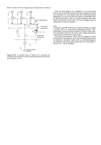
Figure 22.20 A simplified layout of Figure 22.19, illustrating the
sharing of fault current by the station grounding grid and the switchyard
grounding grid on fault