Page 754 - Industrial Power Engineering and Applications Handbook
P. 754

periphery  of  the  grid.  The  ground  current discharging
           20  -- 50                                   through a uniformly spaced ground grid is scanty at the
           25 -- 40                                    centre, dense at the edges and a maximum at the corners.
           30 I-  30                                   Accordingly, the  worst  step and touch  voltages  would
           40 -                                        occur at the outer meshes of  the grid, especially at the
        t  50--  2o                                    corners. To  make the current density  more uniform,  a
                                                       more  non-uniform  conductor  spacing  would  therefore
          loo--  10                                    be necessary with more number of meshes at the centre
        4                                              and fewer towards the periphery. Increasing the number
        i..
        ,o                                             of  meshes,  i.e.  reducing the  conductor spacing, would
        3 200--  5
        2                                              tend to reduce the step and touch voltages until a saturation
        8                                              stage is reached, i.e. when, L, approaches Lc. The factor
        L                                              1.15 may now be increased to 1.2 based on field experience
          400--  2.5                                   and
        .3
          600-
          800 -                                        K, = 0.656 + 0.172 n
         1000  - 1 .o
                                                       where
                                                       n = the number of conductors on each side of  a square
                                                          grid. If the ground grid is not a square and the number
                                                          of conductors lengthwise is IZ, and widthwise nb then
                                                            r
                                                               -
                                                       n = \'ind  . n,,
                                                       Estimating the maximum touch voltage, E,,,
                                                       (actual)
                                                       This will  largely  depend upon  the ratio of  the  current
                                                       densities in the far-end conductors, i.e. conductors at the
                                                       periphery,  and  the  innermost  conductors  and  can  be
                                                       expressed as follows, based on extensive research:


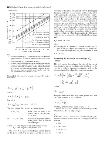
        Figure 22.18  Nomogram  for  conductor  sizing  at  40°C  ambient
        temperature
                                                               K
                                                             + 2 log,
                                                               Kh     n(2n- 1)
                                                       where

        where
         w=;;-+-+-+                                    For grids without or with only a few ground rods near
                            1
                    1
                1
             1
             L  3   4     n-1                          the inner grid (not at the far ends):
                                                       K,  = 41+$
        For n 2 6
         WE-  '  + log, (n - 1)  - 0.423
             2(n - 1)
                                                       where ho is the reference depth of grid = 1  m
        The step voltage falls sharply at higher depths.   The values of Ki and L can be determined along similar
            L = L, + L,      when  there  are  only  a  few   lines to those for the step voltage.
                             ground rods  at the periphery
                             of the grid               Note
                                                       In the above equations  for maximum step and touch voltages  the
        or    = L,  + 1.15L,.   when there are proportionately   best  results will be obtained when  the  following  parameters are
                             more  ground  rods  at  the  far   achieved:
                             end of the grid             n 5 25
        where Lc  = total  length of the grid conductors and   0.25  2 h 5 2.5 m
              L, = total length of the ground rods
                                                         d < 0.25 h  and
          The factor 1.15 represents the higher current density
        in  the  ground  rods  that  are  placed  at the  far  ends  or   D  > 2.5  m
   749   750   751   752   753   754   755   756   757   758   759