
Page 750 - Industrial Power Engineering and Applications Handbook
P. 750
22/71 0 Industrial Power Engineering and Applications Handbook
If there are ti, number of conductors lengthwise and The soil resistance
/ih widthwise and nlf = number of grounding rods used in
V
a grounding grid at a depth of h, then the total length of R =-
the buried conductors I! I,
4 n. , R,
a
L = 12, b + nh . n + rig . h metres (22.13) and p=
2 LE
With an increase in the length of the buried ground 1 +=----L
conductors, the value of their ground resistance diminishes. 4"' + 4b2 <a2 + b'
It has been found that equation (22.13) is more accurate Since generally
for a grid depth up to 250 mm. At greater depths of
station grids, a more accurate representation is found in
the following equation: for accurate results keep b 5 20
1 )] :. p = 2na R, (22.15)
1 + h,i201A- (22.14) The current tends to flow near the surface for smaller
probe spacing and deeply through the soil for larger
spacing. As the soil resistivity may vary widely, it is
22.1 1 Measuring the average recommended that a wider assessment of the soil strata
resistivity of soil be made by varying the probe spacing u and thus
determining the variation in soil resistivity at the location
of the grid. The reflection factor, k, as noted below, forms
It is important to determine the average resistivity of soil an important parameter in the evaluation of a more accurate
at every site where a grounding station is to be located. resistivity of boil where
To do this, a soil test is essential. For this, samples may
P? - P1
be collected from a number of nearby locations at the k=-
site to arrive at an average value. As a result of soil Pz + PI
stratification, samples must be collected at different depths and p1 = resistivity of the upper larger strata of soil and
to ascertain variation in the resistivity to decide on a p2 = resistivity of the lower larger strata of soil
suitable depth for the grounding grid. For simplicity,
Tables 22.1 and 22.2 suggest the likely average range of
resistivity for different kinds of soils and their moisture 22.12 Improving the performance of
conditions.
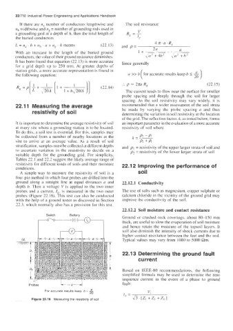
A simple way to measure the resistivity of soil is a soil
four-pin method in which four probes are drilled into the
ground along a straight line at equal distances a and 22.12.1 Conductivity
depth b. Then a voltage V is applied to the two inner
probes and a current, If, is measured in the two outer The use of salts such as magnesium, copper sulphate or
probes (Figure 22.16). This test can also be conducted calcium chloride in the vicinity of the ground grid may
with the help of a ground tester as discussed in Section improve thc conductivity of the soil.
22.3, which normally also has a provision for this test.
22.12.2 Soil moisture and contact resistance
Switch Battery
Ground or crushed rock coverings, about 80-150 mm
thick, are useful to slow the evaporation of soil moisture
and hence retain the moisture of the topsoil layers. It
will also diminish the intensity of shock currents due to
higher contact resistance between the feet and thc soil.
Typical values may vary from 1000 to 5000 Rm.
22.1 3 Determining the ground fault
current
Based on IEEE-80 recommendations, the following
simplified formula may be used to determine the zero
sequence current in the event of a phase to ground
v
Probes L-- 4 fault:
For accurate results keep b 5 3 v,
20 I -
Figure 22.16 Measuring the resistivity of soil " - & ' [Z, + Z? + z, 1