
Page 749 - Industrial Power Engineering and Applications Handbook
P. 749
Grounding practices 22/709
where
d
= ground resistance at the surface of the soil
4 A
and
P
- = ground resistance of the total buried length
(L) of the conductors
R, = station ground resistance in Q
p = average resistivity of soil in Qm
This will depend upon the condition of the
soil and its moisture content. This is why it is
usually high where the moisture content is
less than 15% of the weight of soil. The
variation in soil resistivity is, however, low
when the moisture content exceeds 22%.
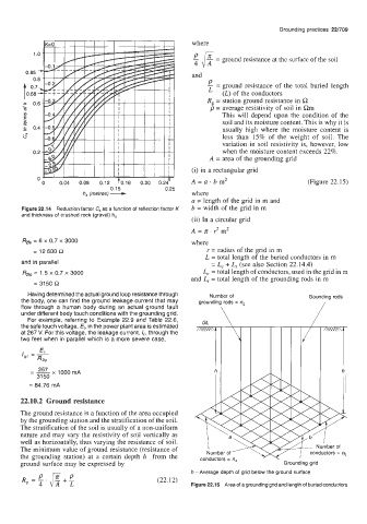
A = area of the grounding grid
(i) in a rectangular grid
hs (metres) - A = u . b m2 (Figure 22.15)
" 0 0.04 0.08 0.12 70.16 0.20 0.247
0.25
0.15
where
a = length of the grid in m and
Figure 22.14 Reduction factor C, as a function of reflection factor K b = width of the grid in m
and thickness of crushed rock (gravel) h,
(ii) In a circular grid
A = a 3 m2
+
Ras = 6 x 0.7 x 3000 where
= 12 600 R r = radius of the grid in m
L = total length of the buried conductors in m
and in parallel = L, + L, (see also Section 22.14.4)
R2fp = 1.5 x 0.7 x 3000 L, = total length of conductors, used in the grid in m
and L, = total length of the grounding rods in m
= 3150 R
Having determined the actual ground loop resistance through Number of Gounding rods
the body, one can find the ground leakage current that may grounding rods = ng
flow through a human body during an actual ground fault 1
under different body touch conditions with the grounding grid. GL \
For example, referring to Example 22.9 and Table 22.6,
the safe touch voltage, Et, in the power plant area is estimated
at 267 V. For this voltage, the leakage current, le, through the
two feet when in parallel which is a more severe case,
-- 267 x 1000 mA
-
31 50
22.10.2 Ground resistance
The ground resistance is a function of the area occupied
by the grounding station and the stratification of the soil.
The stratification of the soil is usually of a non-uniform
nature and may vary the resistivity of soil vertically as
well as horizontally, thus varying the resistance of soil.
The minimum value of ground resistance (resistance of
the grounding station) at a certain depth h from the
ground surface may be expressed by
h - Average depth of grid below the ground surface
Figure 22.15 Area of a grounding grid and length of buried conductors