
Page 746 - Industrial Power Engineering and Applications Handbook
P. 746
22/706 Industrial Power Engineering and Applications Handbook
the grounded grid potential may be regarded as zero, and its duration. In an automatic reclosure power
except transferred voltages and surge pilferages that may system, reclosure after a ground fault is common
be caused during a transient state (Section 18.5.2). During practice in modern power systems. This may result
a ground fault the current will flow through the grounding in repeat shocks in quick succession to a human
grid and cause its potential to rise with respect to a remote body coming into contact with the ground conductor.
ground. This voltage rise is seen to go up to 25 kV, but Although this situation may last for less than 0.5 s,
generally not beyond 10 kV (IEEE 367) and can be it may prove fatal. A reasonable allowance for such
expressed by an eventuality should be made when deciding on
the clearing time.
GPR 0~ I, . R,
where Ig = fault current through the grounding grid Since a switchyard is normally connected to more than
and R, = grid resistance at the station grounding grid, one supply system, the ground fault current in a power
with respect to the remote ground. station is contributed by the power plant as well as by
the switchyard and the transmission networks. The
The larger the grounded grid area, the lower will be the following possibilities may arise:
grid resistance, and the lower the GPR and the mesh
voltage.
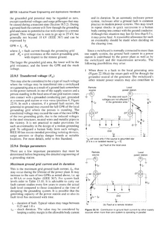
1 When there is a fault in the local generating area
(Figure 22.10(a)) the return path will be through the
22.9.5 Transferred voltage (Etr) grounded neutral of the generator. The switchyard's
This may also be considered to be a type of touch voltage other remote power sources may also contribute to
where the voltage may be transferred into a switchyard
or a generating area as a result of a ground fault somewhere Remote Local
in the power network in one of the supply sources and a source power station
person standing in the local area of one grid station comes
The step and touch
into contact with a grounded conducting part, grounded i.
at a remote grid station or vice versa (position 4, Figure voltages are not affected
22.9). In such a situation, if a ground fault occurs, the in- the generator area + 191
potential to ground may exceed the full GPR of the local L
grounding grid where the person is standing. The
transferred voltage may exceed the sum of the two GPRs GT GT
of the two grounding grids, due to the induced voltages
in the steel structures, neutral wires and metallic pipes in TG L---+
the vicinity. It is not practical to make provisions for I I
grid. To safeguard a human body from such voltages, + 11 I I
such an eventuality in the design of a station grounding
IEEE 80 has recom-mended providing isolating devices, I O/G 11 I1 41 , I I
11
surge arresters or display danger boards at suitable l---------------------------~Lf- 192
locations. For more details, refer to this Standard. 'Ig2 will exist only if the source is grounded star
[If it is A or isolated neutral /g2 = 01
22.9.6 Design parameters (a) Fault at the local area
There are a few important parameters that must be Remote Local
determined before beginning the detailed engineering of source power station
a grounding station.
Maximum ground grid current and its duration
This is the maximum grid ground fault current, IG, that
may occur during the lifetime of the power plant. It may
increase to the sum of two GPRs as noted above, ;.e. up
to 80 kA or even higher (IEEE 367). For system fault
levels refer to Table 13.10. It is advisable to carry out
fault current studies every few years to assess the actual
fault level compared to those considered at the time of
designing the grounding system. It is possible that the
generating capacity of the power station and so also its
fault level has increased with time. OIG
19 1
Y~L------------)-----------------'
t, - duration of fault. Typical values may range between 192
0.25 and 1.0 s (b) Fault at a remote location
tsl - shock duration. The value may be considered by Figure 22.10 Contribution to ground fault currrent by other supply
keeping a safety margin in the allowable body current sources when more than one system IS operating in parallel