
Page 741 - Industrial Power Engineering and Applications Handbook
P. 741
Grounding practices 221701
f
-103
E
A
2.
:
8 10’
c
3
:I
.z 10
d
1 Sod temperature - Effect of salt -
,I
0 10 20 30% -20 O* 20 40 60°C 0 5 10 15% 20%
Content of moisture +
(a) (b) (C)
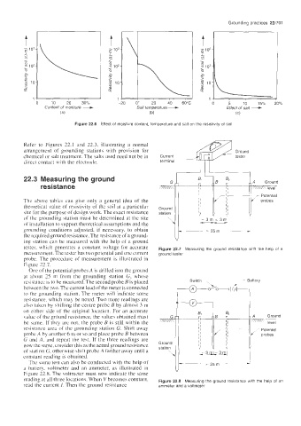
Figure 22.6 Effect of moisture content, temperature and salt on the resistivity of soil
Refer to Figures 22.1 and 22.3, illustrating a normal
arrangement of grounding stations with provision for
chemical or salt treatment. The salts used need not be in
direct contact with the electrode.
22.3 Measuring the ground I Ground
),A
resistance
Thc above tables can give only a general idea of the
theoretical value of resistivity of the soil at a particular
site for the purpose of design work. The exact resistance station
of the grounding station must be determined at the site
of installation to support theoretical assumptions and the
grounding conditions adjusted, if necessary, to obtain
the required ground resistance. The resistance of a ground-
ing station can be measured with the help of a ground
tester. which generates a constant voltage for accurate Figure 22.7 Measuring the ground resistance with the help of a
measurement. The tester has two potential and one current ground tester
probe. The procedure of measurement is illustrated in
Figure 72.7.
One of the potential probes A is drilled into the ground
at ahout 15 m from the grounding station G, whose
resistance is to be measured. The second probe B is placed
between the two. The current lead of the meter is connected
to the grounding station. The meter will indicate some
resistance. which may be noted. Two more readings are
also taken by shifting the centre probe B by almost 3 m
on either side of the original location. For an accurate
due of the ground resistance, the values obtained must A Ground
be same. If they are not, the probe B is still within the ’= level
resistance area of the grounding station G. Shift away Potential
probe A by another 6 m or so and place probe B between probes
G and A, and repeat the test. If the three readings are
now the same. consider this as the actual ground resistance
of station G, otherwise shift probe A farther away until a
constant reading is obtained.
The same test can also he conducted with the help of
a battery, voltmeter and an ammeter, as illustrated in
Figure 22.8. The voltmeter must now indicate the same
reading at all three locations. When Vbecomes constant, Figure 22.8 Measuring the ground resistance with the help of an
read the current I. Then the ground resistance ammeter and a voltmeter