
Page 738 - Industrial Power Engineering and Applications Handbook
P. 738
22/698 Industrial Power Engineering and Applications Handbook
15 mm$ GI
water pipe Wire mesh
Cast iron
I I / chamber cover
0
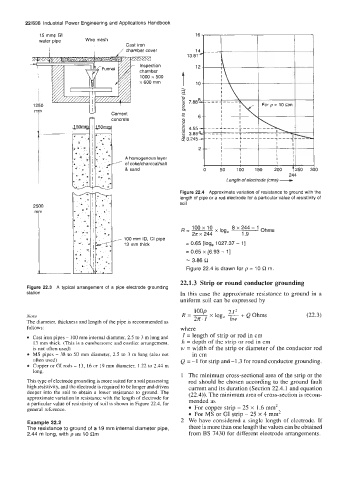
2500 ml Length of electrode (cms) -
1250
Y
Cement
A homogenous layer
of coke/charcoal/salt
& sand
Figure 22.4 Approximate variation of resistance to ground with the
length of pipe or a rod electrode for a particular value of resistivity of
soil 244
R=- 100 x 10 8 x 244 - 1 Ohms
2n x 244 loge 1.9
100 mm ID, CI
13 mm thick = 0.65 [log, 1027.37 - 11
= 0.65 x [6.93 - 11
= 3.86 R
Figure 22.4 is drawn for p = 10 R rn.
22.1.3 Strip or round conductor grounding
Figure 22.3 A typical arrangement of a pipe electrode grounding
station In this case the approximate resistance to ground in a
uniform soil can be expressed by
loop
Note R=- 2n. I x log, + Q Ohms (22.3)
The diameter, thickness and length of the pipe is recommended as
follows: where
Cast iron pipes - 100 mm internal diameter, 2.5 to 3 m long and I = length of strip or rod in cm
13 mm thick. (This is a cumbersome and costlier arrangement, h = depth of thc strip or rod in cm
is not often used) w = width of the strip or diameter of the conductor rod
MS pipes - 38 to 50 mm diameter, 2.5 to 3 m long (also not in cm
often used) Q = -1 for strip and -1.3 for round conductor grounding.
Copper or GI rods - 13, 16 or 19 mm diameter, 1.22 to 2.44 m
long.
1 The minimum cross-sectional area of the strip or the
This type of electrode grounding is more suited for a soil possessing rod should be chosen according to the ground fault
high resistivity, and the electrode is required to be longer and driven current and its duration (Section 22.4.1 and equation
deeper into the soil to obtain a lower resistance to ground. The (22.4)). The minimum area of cross-section is recorn-
approximate variation in resistance with the length of electrode for mended as
a particular value of resistivity of soil is shown in Figure 22.4, for
general reference. For copper strip - 25 x 1.6 mm2
For MS or GI strip - 25 x 4 mm2
Example 22.2 2 We have considered a single length of electrode. If
The resistance to ground of a 19 rnrn internal diameter pipe, there is more than one length the values can be obtained
2.44 rn long, with p as 10 Rrn from BS 7430 for different electrode arrangements.