
Page 743 - Industrial Power Engineering and Applications Handbook
P. 743
Grounding practices 221703
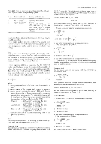
Table 22.4 Size of aluminium ground conductor for different 200 A. To calculate the main ground conductor size, assume
sizes of power cables for a grounding system that the system is protected through HRC fuses. Then, based
on the previous assumptions,
Ground fault current, I, = 3 x 400
1 up to 25 mm’ Same as the cable size = 1200 A
7 Above 25-50 mm’ 25 mm2
3 Above SO mm2 Approximately half the size of the and interrupting time of 400 A HRC fuses, referring to
main cable size. Say. for a 400 characteristic curves of Figure 21.4 = 60 seconds
mm2 main cable, a ground :. Ground conductor size for an aluminium conductor
conductor of 185 mm’, will be
adequate
i.e. 25 mm x 3 mm [ 1” x $1
conductor. For a GI ground conductor, this size may be
roughly doubled.
For large feeders and HT systems the ground fault
current would be controlled naturally through the ground or any other cross-section of an equivalent area
If the conductor is of GI then,
circuit impedance and a smaller ground conductor may
suffice. s=- l2O0 ,/60
80
Note or = 116 mm2
In LT systems, where the neutral is grounded, the neutral as well as
the ground conductor may have to carry unbalanced currents up 10 or 25 mm x 5 mrn (1” x 4”)
half the rating of the line currents due to single-phase loads. A
ground conductor should also he rated for the same size as the or any other cross-section of an equivalent area.
neutral. irrespective of the setting of the relay. It could similarly be calculated for the individual outgoing
circuits, or considered equivalent to half the cable size being
used to feed the circuit.
Now equation (22.4) as suggested by BS 7430 will
apply, which is based on our discussions in Section 2 1.3.1,
where the ground system is normally predetermined for Example 22.5
three times the rated current of the circuit for an HRC If a distribution system is fed from a 1600 kVA, 11 kV/415 V,
transformer, then
fuse-protected system or one and a half times for an over
current release-protected system: 1600 x 1000 A
I, =
x 415
(22.4) = 2225 A
where If the system is protected through overcurrent releases, then
S = crosyectional area of a bare ground conductor in applying the same assumptions as before:
mm- . Ground fault current, I, = 1.5 x 2225 A
!g = r.m.s. value of the ground fault current in amperes
K = r.m.s. current density in A/mm2. This will depend and the maximum tripping time at this current, referring to
upon the material of the conductor and its maximum characteristics curves of Figure 21.3.
permissible temperature. For more common metals = 370 seconds
it may have the following values, assuming the initial
temperature of the conductor to be 4OOC. :. Ground conductor size for an aluminium conductor
Copper = 205 A/mm2, assuming the final 1.5 x 2225 %/m
temperature to be 395°C S= 126
Aluminium = 126 A/mm’, assuming the final
temperature to be 325°C = 509.5 mm2
Steel or GI = 80 A/mm’, assuming the final or 100 mm x 5 mm
temperature to be 500°C
t = duration of fault in seconds (operating time of the or 100 mm x 6 mm
protective device). or any other cross-section of an equivalent area.
If the conductor is of GI then
Note s = 1.5 x 80 2225 ,,m
For other grounding materials. or hazardous locations requiring a
much lower end temperature. refer to BS 7430.
= 802.5 mm2
Example 22.4 or 80 mm x 10 mm or
Consider a power distribution system having the main incoming
feeder rated for 400 A and the outgoing feeders rated up to any other cross-section of an equivalent area.