
Page 739 - Industrial Power Engineering and Applications Handbook
P. 739
Grounding practices 221699
The performance of this type of electrode grounding is
almost the same as for the pipe grounding (Section 22.1.2)
as is the variation in resistance to the ground with the
length of thc clcctrodc as in Figure 22.4.
Example 22.3
The resistance to ground for a 100 mm x 5 mm, 5 m copper
strip, buried at a depth of 1.5 m, having a soil resistivity of
100 ilm
2x500'
R= 100 x 100 X log, ___ -
2 x ilx 500 150 x 10
= 3 185 log, 33333- 1 = 3 185 x 581 - 1
= 17 50 il
If the length of the strip is 25 m. other parameters remaining
the same, then
R= 100 x 100 2 x (2500)' -1
2il~2500~'~~~
150x10
= 0.637 log, 8333.33 - 1
= 0.637 x 9.03 - 1
3
2
0 Number of electrodes (stations) -
4
1
= 4.75 0
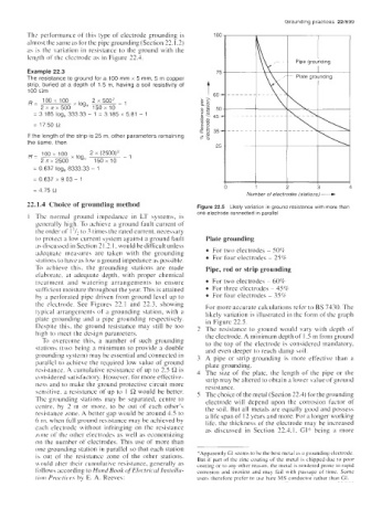
22.1.4 Choice of grounding method Figure 22.5 Likely variation in ground resistance with more than
one electrode connected in parallel
1 The normal ground impedance in LT systems, is
generally high. To achieve a ground fault current of
the order of 1 to 3 times the rated current, necessary
to protect a low current system against a ground fault Plate grounding
a\ discussed in Section 2 1.2. I, would be dificult unless For two electrodes - 50%
adequate measures are taken with the grounding For four electrodes - 256
stations to have as low a ground impedance as possible.
To achieve this. the grounding stations are made Pipe, rod or strip grounding
elaborate. at adequate depth, with proper chemical
treatment and watering arrangements to ensure For two electrodes ~ 60%
sufficient moisture throughout the year. This is attained For three electrodes - 45%
by a perforated pipe driven froin ground level up to For four electrodes - 35%
the electrode. See Figures 22.1 and 22.3, showing For more accurate calculations refer to BS 7430. The
typical arrangements of a grounding station, with a likely variation is illustrated in the form of the graph
plate grounding and a pipe grounding respectively. in Figure 22.5.
Despite this, the ground resistance may still be too The resistance to ground would vary with depth of
high to meet the design parameters. the electrode. A minimum depth of 1.5 in from ground
To overcome this, a number of such grounding to the top of the electrode is considered mandatory.
stations (two being a minimum to provide a double and even deeper to reach damp soil.
grounding system) may be essential and connected in A pipe or strip grounding is more effective than a
parallel to achieve the required low value of ground plate grounding.
resistance. A cumulative resistance of up to 2.5 R is The size of the plate, the length of the pipe or the
considered satisfactory. However, for more effective- strip may be altered to obtain a lowei- balue of ground
ness and to make the ground protective circuit more resistance.
sensitive. a resistance of up to 1 R would be better. The choice of the metal (Section 22.4) for the grounding
The grounding stations may be separated, centre to electrode will depend upon the corrosion factor of
centre. by 2 in or more, to be out of each other's the soil. But all metals are equally good and possess
resistance Lone. A better gap would be around 4.5 to a life span of 12 years and more. For a longer working
6 m, when full ground resistance may be achieved by life, the thickness of the electrode may be increased
each electrode without infringing on the resistance as discussed in Section 22.4.1. GI* being a more
rime of the other electrodes as well as economizing
on the number of electrodes. This use of more than -
one grounding station in parallel so that each station
is out of the resistance zone of the other stations, *Apparently GI seems to be the best metal as B groundiiig electrode.
But if part of the zinc coating of the metal is chipped due to poor
would alter their cumulative resistance, generally as coating or to any other reason. the metal is rendered prone io rapid
follows according to Hund Book ofElectrica1 histullu- corrosion and erosion and may fail with passage of time. Some
lion Pructic.e.s by E. A. Reeves: users therefore prefer lo use hare MS conductor rather than GI.