
Page 737 - Industrial Power Engineering and Applications Handbook
P. 737
Grounding practices 22/697
SECTION I Example 22.1
The resistance to ground for a 600 mrn x 600 mrn plate
grounding, considering a sandy soil, treated artificially and
22.1 Grounding electrodes for having attained an average soil resistivity of 10 Rrn
.=q314
industrial installations and
substations 4 2 x 0.6 x 0.6
= 5.22R
The following are a few types of grounding electrodes If the plate is 1200 rnm x 1200 mm then
commonly used for the grounding of industrial installa-
tions, equipment grounding or small and medium-sized R= J 3.14
sub-stations. 4 2 x 1.2x 1.2
= 2.61 Q
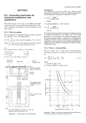
22.1.1 Plate grounding
From the above the resistance to ground of a plate grounding
Refer to Figure 22.1. The approximate resistance to ground is inversely proportional to the square root of the linear
in a uniform soil can be expressed by dimension (a) of the plate. The variation in resistance with
the size of the plate is shown in Figure 22.2. Considering the
R (derived from equation (22.12) (22.1) resistivity of soil as 10 Qm, since the ground resistance is
proportional to the resistivity of soil, there would be different
where p = resistivity of soil, considered uniform in Q m. parallel curves for the ground resistance for different values
A = area of each side of the plate in m2. of resistivity of soil.
Note 22.1.2 Pipe or rod grounding
The minimum thickness of plate is recommended as
Refer to Figure 22.3. In this case, the approximate
For cast iron - 12 mm resistance to ground in a uniform soil can be expressed
For GI or steel - 6.3 mm by:
For copper - 3.15mrn
and size not less than 600 mm x 600 mm 100 .p
R = 2n.I [log, y - 11 R (22.2)
15 mm @GI
water pipe Wire mesh where
I I I = length of pipe in cm
d = internal diameter of pipe in cm
ction chamber
x 500 x 600 mm
A homogenous layer
of coke/charcoal/salt
00 x 1200 x 12 mm
Note
The depth (2000 mm) would vary with the Linear dimensions f&i)(m) --+
moisture content and quality of soil
Figure 22.2 Variation in resistance to ground with the linear dimensions
Figure 22.1 A typical layout of a plate electrode for a plate gounding, for the same resistivity of soil