
Page 732 - Industrial Power Engineering and Applications Handbook
P. 732
21/692 Industrial Power Engineering and Applications Handbook
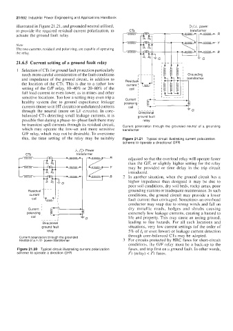
illustrated in Figure 21.21, and grounded neutral utilised, DM Power
to provide the required residual current polarization, to CTs m transformer
actuate the ground fault relay.
'1 s2
Note
The two currents, residual and polarizing, are capable of operating
the relay.
21.6.5 Current setting of a ground fault relay
1 Selection of CTs for ground fault protection particularly
needs more careful consideration of the fault conditions
current 'L
and impedance of the ground circuit, in addition to Residual1
the location of the CTs. This is due to a rather low ~
setting of the G/F relay, 1040% or 20-80% of the coil ,
full load current or even lower, as in mines and other
sensitive locations. Too low a setting may even trip a Current
healthy system due to ground capacitance leakage polarizing I ~
currents (more so in HT circuits) or unbalanced currents coil ~
through the neutral (more on LT circuits). In core- -_----
Directional
balanced CTs detecting small leakage currents, it is ground fault
possible that during a phase-to-phase fault there may relay
be transient spill currents through its residual circuit, Current polarization through the grounded neutral of a grounding
which may operate the low-set and more sensitive transformer
G/F relay, which may not be desirable. To overcome
this, the time setting of the relay may be suitably Figure 21.21 Typical circuit illustrating current polarization
scheme to operate a directional GFR
A /D Power
CTs transformer
adjusted so that the overload relay will operate faster
than the G/F, or slightly higher setting for the relay
may be provided or time delay in the trip circuit
introduced.
2 In another situation, when the ground circuit has a
higher impedance than designed it may be due to
poor soil conditions, dry soil beds, rocky areas, poor
Residua grounding stations or inadequate maintenance. In such
current conditions, the ground circuit may provide a lower
coil fault current than cnvisaged. Sometimes an overhead
conductor may snap due to strong winds and fall on
Current dry metallic roads, hedges and shrubs causing
polarizing extremely low leakage currents, creating a hazard to
coil life and property. This may cause an arcing ground,
leading to fire hazards. For all such locations and
ground fault situations, very low current settings (of the order of
relay 5% of I, or even lower) or leakage current detection
through core-balanccd CTs may be adopted.
Current polarization through the grounded
neutral of aA/D power transformer 3 For circuits protected by HRC fuses for short-circuit
conditions, the G/F relay must be a back-up to the
Figure 21.20 Typical circuit illustrating current polarization fuses, and trip first on a ground fault. In other words,
scheme to operate a direction GFR Pt (relay) < 12t fuses.