
Page 730 - Industrial Power Engineering and Applications Handbook
P. 730
21/690 Industrial Power Engineering and Applications Handbook
equipment or circuits, requiring individual protection.
Figure 21 .I6 illustrates the operation of the relay when
the fault occurs within the protected zone. The scheme
will prevent isolation of the equipment for faults
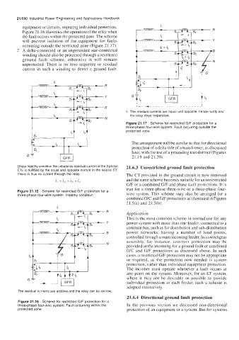
occurring outside the restricted zone (Figure 21.17). 'I
2 A delta-connected or an ungrounded star-connected
winding should also be protected through a restricted
ground fault scheme, otherwise it will remain
unprotected. There is no zero sequence or residual
current in such a winding to detect a ground fault.
B
* The residual currents are equal and opposite, hence nullify and
the relay stays inoperative.
N
Figure 21.17 Scheme for restricted G/F protection for a
three-phase four-wire system. Fault occurring outside the
protected zone
The arrangement will be similar to that for directional
protection of a delta side of a transformer, as discussed
later, with the use of a grounding transformer (Figures
21.19 and 21.20).
Under healthy condition the unbalance residual current of the 3 phase 21.6.3 Unrestricted ground fault protection
CTs is nullified by the equal and opposite current in the neutral CT.
There is thus no current through the relay. The CT provided in the ground circuit is now removed
~ _ ~ _ and the same scheme becomes suitable for an unrestricted
/r + /v + /b = /u
G/F or a combined G/F and phase fault protections. It is
true for a three-phase three-wire or a three-phase four-
Figure 21.15 Scheme for restricted G/F protection for a wire system. This scheme may also be arranged for a
three-phase four-wire system. Healthy condition
combined O/C and G/F protections as illustrated in Figures
21.5(a) and 21.5(b).
Application
This is the most common scheme in normal use for any
power system with more than onc fceder, connected to a
common bus, such as for distribution and sub-distribution
power networks, having a number of load points,
controlled through a main incoming feeder. In a switchgear
assembly, for instance, common protection may be
provided at the incoming for a ground fault or combined
O/C and G/F protections as discussed above. In such
cases, a restricted G/F protection may not be appropriate
or required, as the protection now needed is system
protection, rather than individual equipment protection.
The incomer must operate whenever a fault occurs at
any point on the system. Moreover, for an LT system,
where it may not be desirable or possible to provide
individual protection to each feeder, such a scheme is
adopted extensively.
The residual currents are additive and the relay can be set low.
21.6.4 Directional ground fault protection
Figure 21 .I6 Scheme for restricted G/F protection for a
three-phase four-wire system. Fault occurring within the In the previous section we discussed non-directional
protected zone protection of an equipment or a system. But for systems