
Page 726 - Industrial Power Engineering and Applications Handbook
P. 726
21/686 Industrial Power Engineering and Applications Handbook
-
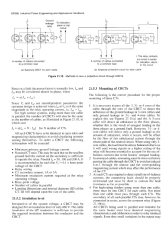
are wired in series
A number of cables connected A number of cables connected * The relay contacts
for indication, alarm
to a common load to a common load or trip circuit.
(a) Separate CBCT for each cable. (b) Separate protective circuit for each cable
Figure 21.10 Methods to wire a protective circuit through CBCTs
Since on a fault the power factor is normally low, Ire and 21.5.3 Mounting of CBCTs
In( may be considered almost in phase, when
The following is the correct procedure for the proper
Ip 2- n(zre +In0 mounting of these CTs:
Since V, and In( are interdependent parameters the
optimum design is achieved when In( at Vr is of the same 1 It is necessary to pass all the 3, 3i or 4 cores of the
magnitude as the relay operating current, i.e. In( 2- Ire. cable through the core of the CBCT to detect the
For high current systems, using more than one cable unbalance or the ground leakage in 3-core cables and
in parallel, the number of CBCTs will also be the same only ground leakage in 33- and 4-core cables. To
as the number of cables, as illustrated in Figure 2 1.10, in explain this see Figures 21.11(a) and (b). A 3-core
which case cable will detect an unbalance in the three phases,
whether this is the result of unequal loading in the
IP = n[/, + N . In(] for N number of CTs three phases or a ground fault. However, 33- or 4-
All such CBCTs have to be identical in turns ratio and core cables will detect only a ground leakage as the
magnetizing characteristics to avoid circulating currents amount of unbalance, when it occurs, will be offset
by the flow of this unbalanced current through the
among themselves. To order a CBCT the following return path of the neutral circuit. When using only 3-
information will be essential:
core cables, the load must be almost balanced otherwise
Minimum primary ground leakage current it will send wrong signals or a higher setting of the
Nominal CT ratio. This may be such that on the smallest relay will become essential to account for the out-of-
ground fault the current on the secondary is sufficient balance currents due to the feeders’ unequal loading.
to operate the relay. Normal I, = SO, 100 and 200 A. It 2 In armoured cables, armouring must be removed before
is recommended to be such that V, 2- 0.1 x knee point passing the cable through the CBCT to avoid an induced
voltage of the CBCT e.m.f. through the armour and the corresponding
Relay setting magnetizing current which may affect the performance
CT secondary current, 1A or SA of the CT.
Minimum excitation current required at the relay 3 As such CTs are required to detect small out-of-balance
operating voltage currents, the connecting leads should be properly
Knee point voltage terminated and must be short to contain the lead
Number of cables in parallel resistance as far as possible.
Limiting dimensions and internal diameter (ID) of the 4 For high-rating feeders using more than one cable,
CT. ID will depend upon the size of the cable. there must be one CBCT for each cable. Not more
than one cable must pass through such CTs. The
21.5.2 Insulation level secondary of all such parallel CTs may, however, be
connected in series, across the common relay (Figure
Irrespective of the system voltage, a CBCT may be 2 1.1 O(a)).
designed for an insulation level of only 660 V. The cable All CBCTs being used in parallel and intended for
insulation of the HT conductor is sufficient to provide the same feeder must have identical magnetizing
the required insulation between the conductor and the characteristics and calibration in order to relay identical
CBCT. signals. Even then small variations in the output may