Page 724 - Industrial Power Engineering and Applications Handbook
P. 724

21/684  Industrial Power Engineering and Applications Handbook
                                                      balance  of  the  system.  Similarly, on  a  single phasing,
                                                      although the balance is upset, there is no current through
                                                      the ground circuit and this  scheme would  not detect a
                                                      single phasing.

                                                      21.3  Ground fault protection in
                                                            hazardous areas
          r
        G'                                             These are highly sensitive areas and a little higher level
                                                       of a ground fault current can be catastrophic. It is therefore
                                                       mandatory at such locations to keep their ground leakage
                                                       current  (rather  than  the  ground fault  currents)  low by
                                                       maintaining  a  certain level of  ground  loop impedance
                                                       and  then  be  able  to  detect  and  isolate  these  currents
                                                       promptly.
                                                        The  leakage  current  at  hazardous  locations  such  as
                                                       refineries,  petrochemical  plants  and  mines  should  not
                                                       exceed  15% of  the rated  current  of  the circuit or  5  A,
                                                       whichever is greater. Table 2 1.3 indicates the maximum
                                                       permissible  ground  leakage  currents  for such  areas  at
                                                       15% of the rated current and the recommended maximum
                                                       ground loop impedances.
                                                        The use of  core-balanced  CTs is quite common  for
                                                       such applications. They are specially designed to detect
                                                       the ground leakage current of a circuit. This ground leakage
                                                       is then used  to trip the faulty circuit through  a ground

                                                       Table 21.3  Maximum impedances of ground loop for protection
                                                       by ground leakage relays in hazardous areas
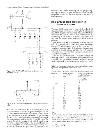
        Figure 21.6  An HT to LT distribution system showing   Current rating   Maximum permissible  Recommended maximum
        grounding circuits                             of circuit   ground leakage   ground loop impedance
                     A>k                                            5              z,  =-  IS xc
                                                                                  on a 240 V phase to
                                                                   currenP 'C'
                                                                   Amp
                                                                                  ground circuitb
                                                       Amp
                                                                                        240
                                                         ~
                                                         5
                                                                                   32
                                                        10
                                                                    5
                                                                                   32
                                                        15
                                     IY
                                          2
                                                        20
                                                                    5
                                                                                   32
                      /E
                                                                    5
                                                        30          5              32
                                                                                   32
                                                        40          6              26.7
                                                        60          9              17.8
                                                        80         12              13.3
                  IR = Iy = /B                         100         15              10.7
                   _..
                 :.  IR + /y + Is = 0                  125         18.7            8.6
                                                       I50         22.5            7.1
        Figure 21.7  Phasor sum of a balanced three-phase system is   175   26.2   6.1
        zero                                           200         30              5.3
                                                       300         45              3.5
                                                       400         60              2.7
        does not necessarily mean that each current phasor R, Y
        or B individually is equal in magnitude and phase. Even   Notes
        if it has unbalanced currents in the three phases (which   aHighly sensitive ground leakage relays can sense a current as low
        is  a  likely  situation  in  a  three-phase system,  see  also   as 0.1 A and less and  at a much higher ground loop impedance.
        Section 12.2(v), it will not cause a current to flow through   bCalculated to  allow  at  least  150% of  the  maximum  permissible
        the ground circuit, as illustrated in Figure 20.19(a). The   current  to  be  on  the  safe  side. For example,  for  15A maximum
        current through the ground circuit will flow only when   ground leakage current, maximum impedance at 240 V
        any one or more of  the phases  has  a ground fault  and
        forms a complete circuit through the ground loop con-   --=  240   10.7 !2
                                                       -
        ductor, as illustrated in Figure 20.19(b), and disturb the   1.5 x 15
   719   720   721   722   723   724   725   726   727   728   729