
Page 729 - Industrial Power Engineering and Applications Handbook
P. 729
Grounding theory and ground fault protection schemes 21/689
21.6.2 Restricted ground fault protection
When it becomes essential to discriminate between a
fault within the circuit to be protected from one outside
the circuit. this scheme may be adopted. While doing so,
it must be ensured that adequate ground fault protection
is available to the remaining feeders, if connected on the
same system.
of residual
For a three-phase three-wire system induced
(generally HT systetns)
The scheme for a three-phase three-wire artificially Impedance
grounded
grounded system will require four CTs, identical in design system
parameters. turn ratio, error and magnetizing character- 7 oh To trw
istics. Otherwise spill currents may occur sometimes
sufficient to operate inadvertently a low-setting or highly
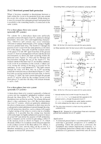
sensitive ground fault relay. The fourth CT through the Note All the four CTs must be wired with the same polarity
ground circuit is used with the same polarity as the three (a) Relay operates when the fault occurs within the protected zone
CTs of the phases. Then only would the residual current
of the phase CTs fall 180" apart from that of the ground Equipment to Direction of
circuit CT. Such an arrangement will provide the desired be protected phase induced
discrimination, to detect the fault occurring within the /' currents in the
protected zone. Figures 21,14(a) and (b) illustrate this
discrimination through the use of the fourth CT. The
residual current of the three-line CT, in a healthy condition,
in the event of an unbalance in the system, is taken care
of by raising the setting of the relay to account for the
unbalance. as in a core-balanced CT. The fault current
through the relay will flow only on a G/F occurring
within the restricted zone as illustrated in Figure 21.14(a).
For faults occurring outside the restricted zone, as shown
in Figure 3 1.14(b), the fault current through the ground
circuit CT will be offset by the residual current of the
three-phase CTs and thus the relay will remain immune
to such a fault.
For a three-phase four-wire system
(generally LT systems) Note All the four CTs must be wired with the same polarity
A three-phase three-wire system is generally a balanced
system and has negligible unbalanced residual current * Induced residual fault current through the phase CTs.
~
_
_
through the three-phase CTs. The relay for a ground (ft = ir + iy + Ib + is equal and falls opposite to the
fault protection can thus be set low. The scheme discussed residual current is through the ground circuit CT.
above is thus satisfactory for a G/F. But in three-phase (7, + 7, + lb) is considered zero under healthy condition.
four-wire LT systems. which are generally unbalanced, For small unbalances the relay is set a little higher.
the above scheme poses a limitation as there may now be
a substantial residual unbalanced current through the relay. (b) The relay stays immune to a fault occurring outside the
For G/F protection. therefore, such a scheme will require protected zone.
a higher setting of the relay to avoid a trip in a healthy Figure 21 .I4 Scheme for a three-phase three-wire restricted
condition. It is possible that this setting may become ground fault protection for an HT system
sufficiently high. for highly unbalanced systems to detect
an actual G/F and defeat the purpose of G/F protection.
Such a situation can be averted by providing a fifth CT Application
in the neutral circuit as shown in Figure 21.15, which 1 A restricted ground fault is recommended for equip-
obviously will have its excitation current direction opposite ment that is grounded, irrespective of its method of
to the residual current of the three-phase CTs. Hence, it grounding. Unless the protection is restricted, the
will offset the bame, and the relay can be set low. It is equipment may remain unprotected. Generally, it is
therefore mandatory to use five CTs in LT systems for an equipment protection scheme and is ideal for the
adequate restricted G/F protection. protection of a generator, transformer and all similar