
Page 731 - Industrial Power Engineering and Applications Handbook
P. 731
Grounding theory and ground fault protection schemes 211691
@---
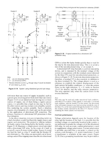
I -L-[ Primary
windings
Residual gw’c i
,/E
~
voltage A
polarizing coil ~
star connected
secondary
Figure 21.19 A typical scheme for a directional GIF
protection relay
GFR to isolate the faulty feeder quickly than to wait for
the trip by the non-directional relay. This is to avoid a
trip of the non-directional relay ‘a’ on system A.
A directional G/F relay basically is a power-measuring
device, and is operated by the residual voltage of the
system in conjunction with the residual current detected
by the three CTs used for non-directional protection, as
Note shown in Figure 21.19. To provide directional protection,
a, b - are non-directional GFR’s therefore, a residual VT is also essential, in addition to
a’, b’- are directional GFR’s the three residual CTs. The voltage phasor is used as a
* Reverse direction current, Iga through relay b would trip breaker reference to establish the relative displacement of the
to
B’ and reduce Iga zero. fault current. In healthy conditions, i.e. when the current
flows in the right direction, V, = 0, (refer to Section
Figure 21.18 System using directional ground fault relays 15.4.3 for details), and the relay remains inoperative.
The relay operates only when the current flows in the
reverse direction.
with more than one source of supply in parallel, such as
a power grid, receiving power from more than one source Note
(Figure 13.21) or an industrial load, having two or more This relay may be used only under unrestricted fault conditions,
sources of supply, one of them being a captive power with three CTs as shown. If the scheme is used under a restricted
source, it is possible that a fault on one may be fed by fault condition, with the fourth CT in the neutral. the directional
the other sources and may isolate even a healthy system, relay will remain immune to any fault occurring outside the zone of
thus rendering the system unstable. Such a situation the three CTs, as the fault current through the fourth CT will offset
the residual current, detected by the three CTY (Section 21.6.3).
requires discrimination of a fault and can be prevented rendering the whole scheme non-functional.
by the application of directional G/F protection. The
primary function of a directional G/F protection is thus Current polarization
discrimination.
In the above situation, even an overspeeding motor on Voltage polarization depends upon the location of the
a fault elsewhere would feed back the supply source and relay and the location of the fault. It is possible that the
require such protection. The protective scheme isolates residual voltage, at a particular location in the system, is
the faulty source from being fed by the healthy sources. not sufficient to actuate the voltage coil of the directional
Figure 21.18 illustrates a simple power circuit provided G/F relay. In such an event, current polarization is used
with a directional G/F relay. In the event of a fault in to supplement voltage polarization. Current polarization
syqtem B, source B alone would isolate. Source A would is possible, provided that a star point is created on the
not feed the fault as relay b’ would trip the breaker B’ system, even through a AID power transformer. if such
and eliminate Iga. The relays are necessarily set at lower a transformer is available in the same circuit, Figure
aettings and at lower tripping times than the non-directional 2 1.20. Else a grounding transformer may be provided as