
Page 728 - Industrial Power Engineering and Applications Handbook
P. 728
21/688 Industrial Power Engineering and Applications Handbook
will be worth while without any serious cost implications. Such Unrestricted G/F protection
a philosophy, however, will not hold good for a system which Directional G/F protection and
is protected only through its incoming feeder and all the outgoing Differential G/F protection (high impedance differential
feeders are merely isolators. In this case the ground leakage protection is discussed in Section 15.6.6(1)).
protection will have to be centralized for the entire system and
provided in the incoming feeder only.
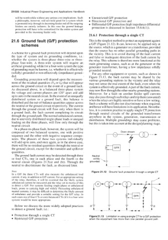
21.6.1 Protection through a single CT
21.6 Ground fault (G/F) protection This is the simplest method to protect an equipment against
schemes a G/F (Figure 21.12). It can, however, be applied only at
the source, which is a generator or a transformer, provided
that the source has no other parallel grounding paths in
A scheme for a ground fault protection will depend upon the vicinity. This is to avoid sharing of the fault current
the type of system and its grounding conditions, i.e. and false or inadequate detection of the fault current by
whether the system is three-phase three-wire or three- the relay. This scheme is therefore more functional at the
phase four-wire. A three-wire system will require an main generating source, such as at the generator or the
artificial grounding while for a four-wire system the type generator transformer, having a low impedance solidly
of grounding must be known, Le. whether it is effectively grounded neutral.
(solidly) grounded or non-effectively (impedance) groun- For any other equipment or system, such as shown in
ded. Figure 21.13, the fault current may be shared by the
Grounding protection will depend upon the measure- various grounding stations in the vicinity and the relay
ment of the residual quantities (Vo or 1,) that will appear may not sense the real extent of the fault, even when the
across the ground circuit in the event of a ground fault. system is effectively grounded. Apart of the fault current,
As discussed above, in a balanced three-phase system may now flow through the other nearby grounding stations.
the voltage and current phasors are 120" apart and add Moreover, for a fault on another feeder spill currents
up to zero in the neutral circuit. In the event of an unequally may also pass through such relays and trip them (unwanted)
distributed system or a ground fault, this balance is when the relays are highly sensitive or have a low setting.
disturbed and the out-of-balance quantities appear across Such a scheme will also not discriminate when required,
the neutral or the ground circuit respectively. The current and hence will have limitations in its application. Neverthe-
through the ground circuit will flow only when there is less, it is common practice to apply single CT protection
a ground fault, the fault current completing its circuit through neutral circuits of the grounded transformers
through the ground path. The normal unbalanced current, anywhere in the system, generation, transmission or
due to unevenly distributed single-phase loads or unequal distribution. Multiple groundings may cause problems,
loading on the three phases, will flow only through the but this is taken into account at the desigdplanning stage.
neutral circuit.
In a phase-to-phase fault, however, the system will be
composed of two balanced systems, one with positive
sequence and the other with negative sequence compo-
nents. The phasors of these two systems individually
will add up to zero, and once again, as in the above case,
there will be no residual quantities through the neutral or
the ground circuit, except for the transient and spillover
quantities.
The ground fault current may be detected through three Neutral
or four CTs, one in each phase and the fourth in the solidly
neutral circuit (Figures 21 S(a) and (b)). Through the grounded \T
neutral to discriminate the fault, as discussed later. i
Note Figure 21.12 Ground fault protection through a single GT
In a G/F the three CTs will also measure the unbalanced load
current, if any, in addition to G/F current. For an appropriate setting
of the relay, therefore, it will be essential that the likely system '
unbalanced current be measured and the relay set in excess of this
to detect a G/F. For systems feeding single-phase or unbalanced
loads, prone to carrying high and widely fluctuating unbalanced
neutral currents, it may be difficult to determine the likely amount
of unbalance and provide a suitable setting for the G/F relay. In
such cases use of four CTs or core-balanced CTs (if it is a four-wire
system) would be more appropriate. I I I
Below we discuss the more widely adopted practices
to detect a ground fault, i.e.:
Protection through a single CT Figure 21.13 Limitation in using a single CTfor a G/F protection
Restricted G/F protection when the equipment has more than one parallel ground path