
Page 723 - Industrial Power Engineering and Applications Handbook
P. 723
Grounding theory and ground fault protection schemes 211683
System or equipment
under protection
R
Y
B
I
1 ,.q &+ 4 4 + 4
-G -G =G -G
(a) (b) (4
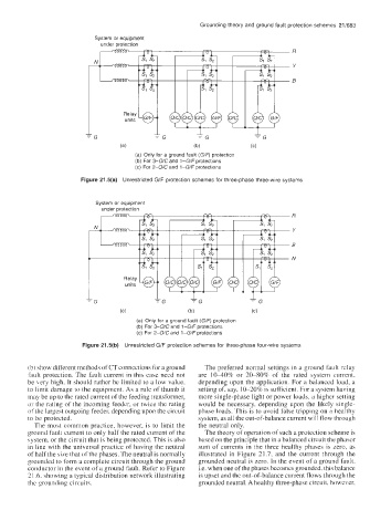
(a) Only for a ground fault (G/F) protection
(b) For 3-0/C and l-G/F protections
(c) For 2-0/C and l-G/F protections
Figure 21.5(a) Unrestricted G/F protection schemes for three-phase three-wire systems
System or equipment
under protection
R
Y
B
N
=G -G
(a) (b) (C)
(a) Only for a ground fault (G/F) protection
(b) For 3-0/C and 1-G/F protections
(c) For Z-O/C and l-G/F protections
Figure 21.5(b) Unrestricted G/F protection schemes for three-phase four-wire systems
(b) show different methods of CT connections for a ground The preferred normal settings in a ground fault relay
fault protection. The fault current in this case need not are 10-40% or 20-80% of the rated system current,
be hery high. It should rather be limited to a low value, depending upon the application. For a balanced load, a
to limit damage to the equipment. As a rule of thumb it setting of, say, IO-20% is sufficient. For a system having
may be up to the rated current of the feeding transformer, more single-phase light or power loads, a higher setting
or the rating of the incoming feeder, or twice the rating would be necessary, depending upon the likely single-
of the largest outgoing feeder, depending upon the circuit phase loads. This is to avoid false tripping on a healthy
to be protected. system, as all the out-of-balance current will flow through
The most common practice, however, is to limit the the neutral only.
ground fault current to only half the rated current of the The theory of operation of such a protection scheme is
system, or the circuit that is being protected. This is also based on the principle that in a balanced circuit the phasor
in line with the universal practice of having the neutral sum of currents in the three healthy phases is zero, as
of half the size that of the phases. The neutral is normally illustrated in Figure 21.7, and the current through the
grounded to form a complete circuit through the ground grounded neutral is zero. In the event of a ground fault,
conductor in the event of a ground fault. Refer to Figure i.e. when one of the phases becomes grounded, this balance
2 1.6. showing a typical distribution network illustrating is upset and the out-of-balance current flows through the
the grounding circuits. grounded neutral. A healthy three-phase circuit. however,