
Page 721 - Industrial Power Engineering and Applications Handbook
P. 721
Grounding theory and ground fault protection schemes 21/681
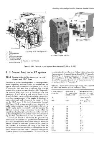
1. Core (Courtesy: MDS switchgear Ltd.)
2. Primaly winding
3. Relay (Courtesy: English Electric)
4. Ground fault indicator
5. Test button tripping
6. Outgoing terminal
they can be interchanged
7. Incoming terminal
Figure 21.2(b) Two-pole ground leakage circuit breakers (ELCBs or GLCBs)
21.2 Ground fault on an LT system current ratings for an LT system. At these values of currents,
the overcurrent releases will trip in about 130-370 seconds.
Refer to ‘Z2 - t’ characteristic curves of such releases as
21.2.1 System protected through over current shown in Figure 21.3. The HRC fuses will blow out in
releases and HRC fuses about 40/60 seconds. Refer to ‘Z2 - t’ characteristic curves
The value of ground loop impedance is always predeter- of fuses, as shown in Figure 21.4.
mined, depending upon the system requirement and the
type of protection available to the system, its accuracy Table 21.2 Maximum impedances of ground loop, when protected
to detect the fault and time to operate. For systems by overcurrent releases of circuit breakers or fuses
protected through overcurrent releases or HRC fuses only,
the ground loop must have a comparatively low Current rating of Overcurrent of Maximum desirable
impedance of ground
the circuit breaker
impedance. It will allow a high ground fault current circuit fuse MCCB or ACB fault loop on a 240 V
through the faulty circuit, sufficient to trip the over current-
cum-short-circuit releases of the breaker if the circuit is ‘a’ ‘b’ circuit (415/&)
protected through such releases of the breaker or blow 240
z, = ~ 3a or 1.5b
out the HRC fuses, if the circuit is protected through
HRC fuses. Such a requirement is more desirable for R
higher rating systems, where discrimination between a 5 10 16
healthy and a faulty condition by such devices may be 10 20 8
difficult. Medium-rating systems may cause a relatively 15 30 5.3
much higher fault current and be automatically protected, 20 40 4
as the normal ground fault current would be sufficient to 30 60 2.7
trip the short-circuit releases or blow out the HRC fuses. 40 80 2
The rule of thumb to determine the ground loop 60 120 1.33
80
impedance is to consider the ground fault current as one 100 160 1
0.8
200
and a half times that of the overcurrent setting of the circuit 125 250 0.64
breaker for breaker-controlled systems (a fault condition 150 300 0.53
for a breaker) or three times the rating of the fuses, for 175 350 0.46
fuse-protected systems (an overcurrent condition for the 200 400 0.4
fuses). Based on this rule, Table 21.2 suggests the optimum 300 600 0.27
values of ground loop impedances for circuits of different 400 etc. 800 etc. 0.2