
Page 747 - Industrial Power Engineering and Applications Handbook
P. 747
Grounding practices 221707
this fault as illustrated, provided that they are grounded Remote Local
star. An isolated star or delta-connected source will source power station
remain unaffected by remote faults. See also Table
13.5 for more clarity. The step and touch voltages in
the generator area will not be affected. The GT
(generator transformer) area and the nearby steel
structures will develop high step and touch voltages.
2 Similarly, when a fault occurs some distance from
the generating area, this area will feed the remote
fault as did the remote sources in the generator area
in the previous case, thus, developing step and touch
voltages in the GT area (Figure 22.10(b)).
The flow of circulating currents in the grounding
conductors or ground of region two caused between
two or more interconnected grounding stations, for a
fault occurring in region one is termed the telluric
effect. I
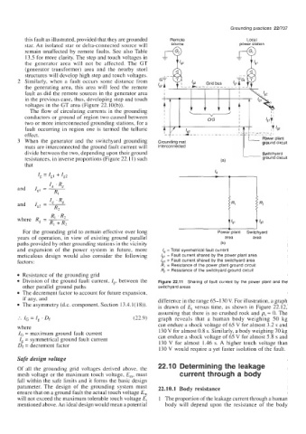
3 When the generator and the switchyard grounding Power plant
ground circuit
mats are interconnected the ground fault current will
divide between the two, depending upon their ground 1 Switchyard
resistances, in inverse proportions (Figure 22.1 1) such (a) ground circuit
that
I, 'R,
and I,, = -
Rl
I, 'R,
and I,, = -
R2
R, 'R2
where R, = ~
R, +R2
For the grounding grid to remain effective over long Power plant Switchyard
years of operation, in view of existing ground parallel area area
paths provided by other grounding stations in the vicinity (b)
and expansion of the power system in future, more I, = Total symmetrical fault current
meticulous design would also consider the following Igl = Fault current shared by the power plant area
factors: /g2 = Fault current shared by the switchyard area
R, = Resistance of the power plant ground circuit
4 = Resistance of the switchyard ground circuit
Resistance of the grounding grid
Division of the ground fault Current, 1,. between the Figure 22.11 Sharing of fault current by the power plant and the
other parallel ground paths switchyard areas
The decrement factor to account for future exDansion,
assuming that there is no crushed rock and ps = 0. The
graph reveals that a human body weighing 50 kg
can endure a shock voltage of 65 V for almost 3.2 s and
where 130 V for almost 0.8 s. Similarly, a body weighing 70 kg
IG = maximum ground fault current can endure a shock voltage of 65 V for almost 5.8 s and
Ig = symmetrical ground fault current
Df = decrement factor 130 V for almost 1.46 s. A higher touch voltage than
130 V would require a yet faster isolation of the fault.
Safe design voltage
22.1 0 Determining the leakage
Of all the grounding grid voltages derived above, the
mesh voltage or the maximum touch voltage, E,,,, must current through a body
fall within the safe limits and it forms the basic design
parameter. The design of the grounding system must 22.10.1 Body resistance
ensure that on a ground fault the actual touch voltage E,,,
will not exceed the maximum tolerable touch voltage E, 1 The proportion of the leakage current through a human
mentioned above. An ideal design would mean a potential body will depend upon the resistance of the body