
Page 748 - Industrial Power Engineering and Applications Handbook
P. 748
22/708 Industrial Power Engineering and Applications Handbook
2 To determine the total resistance of the ground circuit
through the human body, the following may be adopted.
R2rs = resistance between the two feet in series
RZfp = resistance between the two feet in parallel
There are many formulae to determine the above, all
leading to almost the same results. The most adopted,
assuming a layer of crushed rock (gravel) over the
ground surface, is expressed by
R2fs = 6 . c\ . P.;
and total touch resistance RZfsb through the body
RZfsb = ' cs ' Ps -k Rb
= 6 . C, . ps + 1000 (22.10)
and RZfp = 1.5 x C, . p,
and total step resistance, R2fp,, through the body
Allowable fime (sec.) --t
R2fp, = 1.5 x C, . p, + Rb
Figure 22.12 Limits of touch voltages as a function of time
= 1.5 x c, ' p\ + 1000 (22.1 1)
where Rb = body resistance
compared to the resistance through the ground. To
determine the likely body current it is therefore essential = 100OQ
to determine the average body resistance. On this
subject many studies have been made and the following C, = reduction factor for derating the nominal
data established (Figure 22.13): value of surface layer resistivity, correspond-
ing to a crushed rock layer of thickness h,
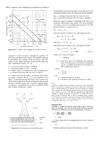
a = resistance hand to hand = 2300 R and a reflection factor k
b = resistance hand to feet = 1130 R where
(A leather shoe is considered as a part of the body) P - PI
c = resistance between the two feet =lo00 Q k= -
P + Ps
It is observed that the body's resistance diminishes and
at higher voltages, above 1 kV and currents more p = ground resistivity in Riii
than 1 A, passing through the body, due to a puncture p\ = crushed rock (gravel) resistivity in Rm
of the skin tissues. For all safety measures and ground
design consideration, the average human body Note
resistance is considered universally, as 1000 R which To achieve a liigli contact rcsiatancr ah a measure to provide higher
has yielded satisfactory results. safety to personnel working in the power plant and switchyard
areas. common practice is to spread a layer of concrete or crushed
rocks (gravel) over the finished ground surface. In the power plant
area. a layer of concrete ( 150-300 mm, depending upon the station
voltage) is spread to provide a resistivity of nearly 500 Rm or
more. In the switchyard area. a layer of crushed rocks is spread
(75-150 mm) to provide a resistivity of nearly 2500-3000 Rm or
more. The value of C, can be read from the h, versus K curves
provided by IEEE 80, as in Figurc 22.14.
Example 22.6
Consider a large sub-station grounding system, having a
layer of crushed rock, 150 mm thick at the surface, having a
resistivity of 3000 Rm and the soil resistivity of 150 Rm:
:. k = 150 - 3000 - 2850
150 + 3000 31 50
Crushed = - 0.90
T rock
:. C, from Figure 22.14, corresponding to a rock surface of
150 mm
/-SOll
= 0.7
Figure 22.13 Resistances of different body parts :. Ground resistance between the two feet in series