
Page 753 - Industrial Power Engineering and Applications Handbook
P. 753
Grounding practices 22/713
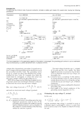
Example 22.8
To determine the minimum size of ground conductor, consider a station grid made of Z, coated steel, having the following
parameters:
Parameters AS in /€€€-80 As in IS 3043
1 or 0.001 kA 1 or 0.001 kA
(to calculate a generalized factor in rnm2/A) (to calculate a generalized factor in rnm'1A)
1 1
0.0032 0.0045
20.1 13.8
3.931 3.8
41 9 450
40 40
__- 20 ~- 20
0.0032 0.0045
= 293 (Table 22.5) = 202
. A= ~ 0 001 0 001
~~
~
3.8 x lo4-
1' i/3931 00032x20 1 ) loge ( 233 < 40 ] /[ 0 0045 x 13 8 1 loge [ ?:2',=?: 1
293 + 419
xlo
0 001 0.001
- -
,O 0061 log, 2 14 I 0.006 log, 2.69
- 0 001 - 0.001
- ~~~~ ~
I 0 6061 x 0 76 \ 0.006 x 0.99
= 0.0147 mm'IA = 0.01 23 rnm'1A
or ~ =68A/mm2 or ~ =81 Nmrn'
0.0147 0.0123
Say 80 Almm'
For an /g of 30 kA,
size of ground = 0.0147 x 30 000 = 0.0123 x 30 000
conductor = 441* mrn' = 369* mrn'
*If a future expansion in the generating capacity of the station is envisaged, the grounding grid conductor size so estimated
may be enhanced by a suitable decrement factor, Df (Section 22.9.6)
voltages that a human body can endure. In actual service The touch voltage diminishes up to 1 m depth
these voltages of the grounding station should not exceed of the grid and then rises rapidly. The ideal
the prescribed tolerable limits. Thc grounding station depth for economic considerations may be taken
design as carried out above must therefore be counter- as 0.5 m when the touch and step voltages are
checked for these limits. If it exceeds these limits the reasonably low.
station must be redesigned, to contain the actual step Ki = corrective factor, accounting for the increase
and touch voltages within the prcscribcd Icvcls. in current densities at the far ends of the grid
IEEE-80 has suggested the following formulae in terms system, the resistivity of the soil and the average
of ground current and total length of buried conductors current density per unit length. Zti/L. of buried
to determine the actual step and touch voltages: conductors.
I, = maximum fault current contributed by the power
p' K, . K, . IC generating units.
Max. step voltage E,(actual) = (22.17)
L L = total length of the buried conductors of the
and mesh or maximum touch voltage E,,(actual) grounding station (equation (22.13)).
(22.18) Estimating the step voltage E, (actual)
In this case
where
p = resistivity of- the soil
K,. K,,, = geometrical factors, depending upon the more
important parameters such as area of the
grounding grid, its depth and conductor spacing and the maximum step voltage is assumed to occur at
and less important factors, such as diameter of a distance equal to grid depth h. where /z is more than
the conductors and the thickness of the finishing 0.25 m and less than 2.5 m. Depths less than 0.25 m may
surface by concrete or gravel. be rare: