
Page 758 - Industrial Power Engineering and Applications Handbook
P. 758
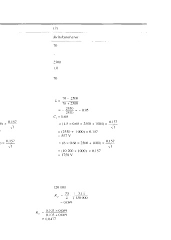
Table 22.6  Safe (tolerab1e)potential difference


 1  (i)   ~  Soil resistivity, p   L2m   ~  70
 (ii)   ~  Surface resistivity  for cnncrctc  of thicl\ne\\  /I,   ~
 ab 250 mm, p\,   <I111   550
 (iii)  Surface resistivity  for gravel of thicknc\\  h, a\
 1 50  rnm, ps2   Qn1   -   2500
 Duration of fault   5  i  I .o   I .0
 1  (maximum clearing time of  the interrupting  device) 1
 I
 Averdge weight of  a huinaii body  (kg)   70   70
 :.  Safe touch  voltage.
 0 157
 E, = (I s c,  p, + inno)  x
 \t
 70 - 550                  70 - 2500
 i  Reflection tactor   k=-   k=  ~
 70 + 550                  70 + 2500
 = -- 4*0  = -0.77        =  -~
                             2430  = - 0.95
 620                         2570
 :.  C, from Figure 22.14   C, = 0.85   C, = 0.68
     0.157
 :.  E,   = (1.5  x 0.85  x 550 + 1000) x  ~
     \/ 1
 = (701.25 + 1000) x 0.157   = (2550 +  1000) x n. I 57
 = 267 V                  = 557 v
 0.157   0.157            = (6 x O.6X x 2500 + 1000) x o.157
 Step voltage,  E,  = (6  c,  p> + 1000) x  T   = 16. x 0.85 x 550 + 1000) x  ~   \'7
 \'  f                                         ;I
 = (2805 +  1000) x 0.157   =(l0200+ 1000)  ~0.157
 = 591 V                  = 1758V
 -
 ,  Ground re\istance (62)
 R,> =   /L (equation (22.12)) L  being  Iargc
 =   4\A
 1  therefore
 i\ ignored  cor eax of calculation
 1  knuinption\ hy  experience: Area   90 000   120 000
 ~
 Ground rcsi\rancc

 '  Total ground  resistance of  power plant  and   0.103  x 0.089
 '  switchyard areas interconnecled  in   K,, =  0.103 + 0.089
 parallel  (recommended practice) where   12   = 0.0177