Page 752 - Industrial Power Engineering and Applications Handbook
P. 752
22/71 2  Industrial Power Engineering and Applications Handbook
        22.14  Designing a grounding grid              humid environment, ground electrodes, being one example.
                                                       It is therefore mandatory that certain corrosion margins
                                                       are considered when choosing the size of ground electrodes
        22.14.1  Minimum size of grid conductors       to account for this in the long run, particularly during the
                                                       considered life span of the generating station, switchyard
        This can be calculated from the formula derived by Sverak   or sub-stations. Handbooks on corrosion suggest likely
        and recommended by IEEE-80:
                                                       corrosion depths. For steel this is considered to be around
                                                       2.2% per year. For GI it will be much less. Considering
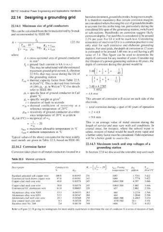
        A=  ,          I,                     (22.1 6)   economics of steel over GI it is a common practice to use
                                                       only steel for such extensive and elaborate  grounding
                                                       stations. For steel grids, the depth of corrosion in 12 years
                                                       is estimated to be around 3.48 mm in a soil having a pH
        where                                          value of  7.4. This figure can be  used to determine the
                A = cross-sectional area of ground conductor   depth of corrosion for any number of years. Consider-ing
                    in mm2                             the lifespan of a power generating station as 40 years, the
                I,  = ground fault current in kA (r.ni.s.)   depth of corrosion during this period would be
                    This may be substituted with the estimated
                    maximum ground grid current, IG (Section
                    22.9.6), that may occur during the life of
                    the grounding station                   1   1  1
                                                            -+-+-+...-
               Tcap = thermal capacity factor from Table 22.5,   i  2  3  12
                                                            1
                    in J/cm3/"C. This is derived from formula
                    (4.184) ph . ps in Ws/cm'/  "C (for details   - 3.48 x 4.2785
                                                       -
                    refer to IEEE-80)                       3.1032
                ph = specific heat of ground conductor in Cal/   = 4.8 mm
                    gram/ "C
                ps = specific weight in g/cm'          This amount of corrosion will occur on each side of the
                 t = duration of fault in seconds      electrode,
               yo = thermal  coefficient  of  resistivity  at  a   :.  total corrosion during a span of 40 years of operation
                    reference temperature of 20°C
               p2,, = resistivity of ground conductor at a refer-   = 2 x 4.8
                    ence temperature of  20°C in ,U R/cm
                                                         = 9.6 mm
         KO (at 0°C) = reciprocal of  w0
                  -  I    20                           This  is  an  average  value  of  metal  erosion  during  the
                    Dc                                 length of service and may vary with soil conditions. In
                      20
               tmax = maximum allowable temperature  in  "C   coastal  areas,  for  instance,  where  the  subsoil water  is
               tamb = ambient temperature in "C        saline, erosion of  metal  would be much more rapid and
                                                       a further safety factor must be considered. Field experience
        Typical values of the above constants for the most widely   will be a better guide to assess this.
        used metals are given in Table 22.5, based on IEEE-80.
                                                       22.14.3  Maximum touch and step voltages of a
         22.14.2  Corrosion factor                            grounding station
         Corrosion takes place in all metal conductors located in 3   In Section 22.8 we discussed the tolerablc step and touch

         Table 22.5  Material constants
                                                            [ -:,,  1
         Description                Conducrivit>        K,, =  - 20     t,,,.   Fusing   PZO   Tcup
                                                                -
                                    8          a20                      temperatiire "C  pWcm   J/tm-'/"C
         Standard annealed  soft copper wire   100 0   000393   234     1083         17241   3422
         Commercial hard drawn copper wire   97 0   000381   242        1084         17774   3422
         Copper-clad  steel core wire   40 0   000778   245             1084/1300    4397   3 846
         Copper-clad steel core wire   30.0    0.00378   245            I084/1300    5.862   3.846
         Commercial EC aluminium wire   61.0   0.00403   228             657         2.862   2.556
         -                        ~~~   ~~   ~~   ~    -
         Aluminium alloy wire 5005   53.5      0.00353   263             660         3.2226   2.598
         Aluminium  alloy wire 6201   52.5     0.00347   268             660         3.2840   2.598
         Aluminium-clad steel core wire   20.3   0.00360   258           660/1300    8.4805   2.670
         Zinc-coated steel core wire   8.5     0.00320   293             41 9/1300   20.1   3.931
         Stainless steel No.  304     2.4      0.00130   149            1400        72.0    4.032
         Refer to Figure 22.18 giving the nomograms for more widely used metals to determine the size of conductor A in terms of duration of fault.

