
Page 751 - Industrial Power Engineering and Applications Handbook
P. 751
Grounding practices 22/71 1
where each generator and the GT at point 6, considering the lower
1, = symmetrical r.m.7. value of the zero sequence fault value of the impedances to be on the safe side,
current
Vt = line voltage = (16 - 1.6) + (14 - 1.4)- 200
250
Z, = positive sequence equivalent system impedance,
Q/phase at the location of the fault = 14.4 + 10.08
Z7 = negative sequence equivalent system impedance, = 24.48%
Q/phase at the location of the fault.
Z,, = zero sequence equivalent system impedance, a/ Since all three generators are operating in parallel, the
phase at the location of the fault. impedance of each circuit, as calculated above, will fall in
parallel and the equivalent impedance will become
It is also possible to estimate this, if the system unit _- +-+- 1 1
1 --
impedance is known, when the maximum fault current Z,, 24.48 24.48 24.48
Full load current of the system 24.48
3
= Unit impedance of the system or z,, = -
= - 100% (13.5) or 8.16% (0.0816 P.u.)
1
x
Z,l Full load current at base MVA
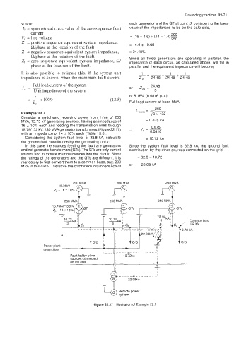
Example 22.7
Consider a switchyard receiving power from three of 200
MVA, 15.75 kV generating sources, having an impedance of = 0.875 kA
16 5 10% each and feeding the transmission lines through 0.875
15.75/132 kV, 250 MVA generator transformers (Figure 22.1 7) :. I - -
with an impedance of 14 f 10% each (Table 13.8). ' - 0.0816
Considering the system fault level at 32.8 kA, calculate = 10.72 kA
the ground fault contribution by the generating units;
In this case the sources feeding the fault are generators Since the system fault level is 32.8 kA, the ground fault
and not generator transformers (GTs). The GTs are only current contribution by the other sources connected on the grid
limiters and introduce their reactances into the circuit. Since
the ratings of the generators and the GTs are different, it is = 32.8 - 10.72
mandatory to first convert them to a common base, say, 200
MVA in this case. Therefore the combined unit impedance of or 22.08 kA
200 MVA 200 MVA 200 MVA
15.75kV
-
-
I
250 MVA 250 MVA 250 MVA
1L 4
I
lO/G
-
Power plant - I - -
i-l
ground bus T 1 I ____ __-_ - ___-- 11 ,
~
Fault fed by other ~ 10.72kA I
sources connected I
on the grid I I i
-
5
I
l
I ______- -1
Figure 22.17 Illustration of Example 22.7