
Page 878 - Industrial Power Engineering and Applications Handbook
P. 878
26/830 Industrial Power Engineering and Applications Handbook
up to 150% of the rated current continuously and operate Protection with internal fuses is easier, as fuses are
for a few seconds at 300%. Refer to Figure 2 1.4 for provided for each element which can contain the severity
typical current-time curves of HRC fuses. Use of an of the fault well within the safe zone in all probability.
IDMT relay with an appropriate setting will also be Some users even recommend capacitor units 250/300
good practice in such cases. kVAr and above with internal fuses only. Figure 26.1
For-delta connected capacitor units: In this case, it shows a typical operating band of the internal fuses for
will establish a line-to-line fault with a heavy fault an internally protected unit. It demonstrates a sufficient
current. Protection by HRC fuses would be more margin between the operation of the fuses and the shell’s
appropriate than for a grounded star or using an MCCB. safe zone. The fuse characteristics are almost the same
For series-parallel connected units: This is applicable for all manufacturers.
in HT capacitor banks comprising a numher of small Since such explosions are dangerous and may cause a
units arranged in series and parallel combinations. The fire hazard through the dielectric liquid which may be
fault current in such cases for an isolated neutral can inflammable, it is imperative that such faults are cleared
be expressed by before they may result in bursting of the shell. They will
require short-circuit protection. Leading manufacturers
I,-=-. 3N, Nl (from equation (25.3)) producing units suitable for external protection provide
3N, -2 I‘ a pressure-sensitive disconnector which operates and
Now also an IDMT relay would provide the most releases the pressure during a fault when the inside
appropriate protective scheme. pressure builds up to a preset level. This may be in the
form of expandable bellows, which expand on such
To summarize, HRC fuses or fuse-free MCCBs for LT excessive pressures inside and snap open the power
and a breaker and IDMT relay arranged for 2 O/C and connections. Safety through expansion bellows is usually
1 G/F, with a short-circuit unit for HT capacitor banks, a feature in LT, MPP capacitors. In HT this technology is
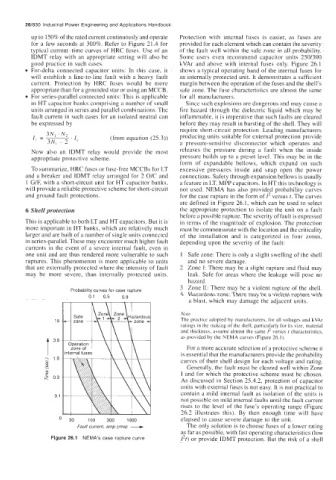
will provide a reliable protective scheme for short-circuit not used. NEMA has also provided probability curves
and ground fault protections. for the case rupture in the form of 1’ versus 1. The curves
are defined in Figure 26. I, which can be used to select
6 Shell protection the appropriate protection to isolate the unit on a fault
before a possible rupture. The severity of fault is expressed
This is applicable to both LT and HT capacitors. But it is in terms of the magnitude of explosion. The protection
more important in HT banks, which are relatively much must be commensurate with the location and the criticality
larger and are built of a number of single units connected of the installation and is categorized in four zones,
in series-parallel. These may encounter much higher fault depending upon the severity of the fault:
currents in the event of a severe internal fault, even in
one unit and are thus rendered more vulnerable to such 1 Safe zone: There is only a slight swelling of the shell
ruptures. This phenomenon is more applicable to units and no severe damage.
that are externally protected where the intensity of fault 2 Zone I: There may be a slight rupture and fluid may
may be more severe, than internally protected units. leak. Safe for areas where the leakage will pose no
hazard.
3 Zone 11: There may be a violent rupture of the shell.
Probability curves for case rupture
0.1 0.5 0.9 4 Hazardous zone: There may be a violent rupture with
a blast, which may damage the adjacent units.
I Safe I Yqlt Note
10 The practice adopted by manufacturers, for all voltages and kVAr
ratings in the making of the shell, particularly for its size, material
and thickness, assume almost the same I‘ versus t characteristics,
as provided by the NEMA curves (Figure 26.1).
For a more accurate selection of a protective scheme it
t 3’0 is essential that the manufacturers provide the probability
-. 1.0 curves of their shell design for each voltage and rating.
m
E Generally, the fault must he cleared well within Zone
m I and for which the protective scheme must be chosen.
E 0.3
As discussed in Section 25.4.2, protection of capacitor
units with external fuses is not easy. It is not practical to
contain a mild internal fault as isolation of the units is
0.1
not possible on mild internal faults until the fault current
rises to the level of the fuse’s operating range (Figure
Fault current, amp (rms) - 26.2 illustrates this). By then enough time will have
I 30 100 300 1000 elapsed to cause severe damage to the unit.
The only solution is to choose fuses of a lower rating
as far as possible, with fast operating characteristics (low
Figure 26.1 NEMA’S case rupture curve 1*t) or provide IDMT protection. But the risk of a shell