
Page 959 - Industrial Power Engineering and Applications Handbook
P. 959
(made of foils or braids) ~ -
Recommended practices buses and making bus joints 291909
Cu or AI flexible connector Spring washer ~~ Plain washer
M Plain washeri
Rivets to hold the ~~
Main bus flexible wram 1 r- Slots (11 x16)
~
45 -z= 90 --
-
45
L One section It Second section -
of bus of bus
Tap-off links (All dimensions in mm)
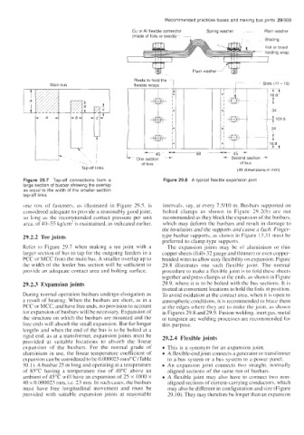
Figure 29.7 Tap-off connections from a Figure 29.8 A typical flexible expansion joint
large section of busbar showing the overlap
as equal to the width of the smaller section
tap-off links
one row of fasteners, as illustrated in Figure 29.5, is intervals, say, at every 75/10 in. Busbars supported on
considered adequate to provide a reasonably good joint, bolted clamps as shown in Figure 29.2(b) are not
so long as the recommended contact pressure per unit recommended as they block the expansion of the busbars.
area. of40-55 kg/cm' is maintained, as indicated earlier. which may deform the busbars and result in damage to
the insulators and the supports and cause a fault. Finger-
29.2.2 Tee joints type busbar supports, as shown in Figure 13.3 1 must be
preferred to clamp type supports.
Refer to Figure 29.7 when making a tee joint with a The expansion joints may be of aluminium or thin
larger section of bus to tap for the outgoing feeders in a copper sheets (foils 32 gauge and thinner) or even copper-
PCC or MCC from the main bus. A smaller overlap up to braided wires to allow easy flexibility on expansion. Figure
the width of the feeder bus section will be sufficient to 29.8 illustrates one such flexible joint. The normal
provide an adequate contact area and bolting surface. procedure to make a flexible joint is to fold these sheets
together and press clamps at the ends, as shown in Figure
29.2.3 Expansion joints 29.9, where it is to be bolted with the bus sections. It is
riveted at convenient locations to hold the foils in position.
During normal operation busbars undergo elongation as To avoid oxidation at the contact area, when it is open to
a result of heating. When the busbars are short, as in a atmospheric conditions, it is recommended to brace them
PCC or MCC, and have free ends, no provision to account at the edges where they are to make the joint, as shown
for expansion of busbars will be necessary. Expansion of in Figures 29.8 and 29.9. Fusion welding, inert gas, metal
the structure on which the busbars are mounted and the or tungsten arc welding processes are recommended for
free ends will absorb the small expansion. But for longer this purpose.
lengths and when the end of the bus is to be bolted at a
rigid end, as at a transformer, expansion joints must be 29.2.4 Flexible joints
provided at suitable locations to absorb the linear
expansion of the busbars. For the normal grade of This is a synonym for an expansion joint.
aluminium in use, the linear temperature coefficient of 0 A flexible-end joint connects a generator or transformer
expansion can be considered to be 0.000023 rnm/"C (Table to a bus system or a bus system to a power panel.
30.1 ). A busbar 25 m long and operating at a temperature An expansion joint connects two straight, normally
of 85°C having a temperature rise of 40°C above an aligned sections of the same run of busbars.
ambient of 45°C will have an expansion of 25 x 1000 x A flexible joint may also have to connect two non-
40 x 0.000023 mm. i.e. 23 mm. In such cases, the busbars aligned sections of current-carrying conductors. which
must have free longitudinal movement and must be may also be different in configuration and size (Figure
provided with suitable expansion joints at reasonable 29.10). They may therefore be longer than an expansion