
Page 956 - Industrial Power Engineering and Applications Handbook
P. 956
29/906 Industrial Power Engineering and Applications Handbook
Bolt head
Plain washer ,-20 + 3-, Shank
Min. 2 threads
to protrude
Figure 29.2(a) Correct procedure for using a bolt and nut
assembly
Plain washer
Busbar-
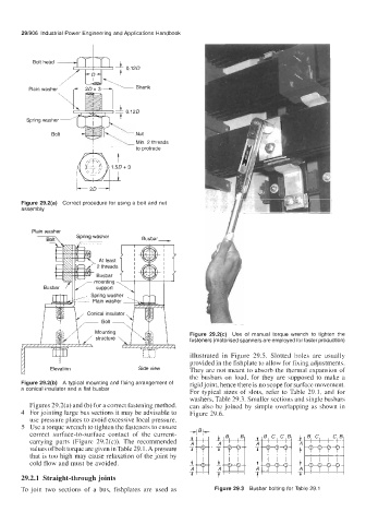
Figure 29.2(c) Use of manual torque wrench to tighten the
fasteners (motorised spanners are employed for faster production)
illustrated in Figure 29.5. Slotted holes are usually
provided in the fishplate to allow for fixing adjustments.
Elevation Side view They are not meant to absorb the thermal expansion of
the busbars on load, for they are supposed to make a
Figure 29.2(b) A typical mounting and fixing arrangement of rigid joint, hence there is no scope for surface movement.
a conical insulator and a flat busbar
For typical sizes of slots, refer to Table 29.1, and for
washers, Table 29.3. Smaller sections and single busbars
Figures 29.2(a) and (b) for a correct fastening method. can also be joined by simple overlapping as shown in
4 For jointing large bus sections it may be advisable to Figure 29.6.
use pressure plates to avoid excessive local pressure.
5 Use a torque wrench to tighten the fasteners to ensure
correct surface-to-surface contact of the current-
carrying parts (Figure 29.2(c)). The recommended
values of bolt torque are given in Table 29.1. A pressure
that is too high may cause relaxation of the joint by
cold flow and must be avoided. i
A
7
29.2.1 Straight-through joints
To join two sections of a bus, fishplates are used as Figure 29.3 Busbar bolting for Table 29.1