
Page 955 - Industrial Power Engineering and Applications Handbook
P. 955
Recommended practices buses and making bus joints 291905
29.1 Precautions in mounting and a humming noise due to magnetic inductance.
insulators and conductors This may lead to loosening of fasteners and be
detrimental to the performance of the busbar system
in the long run. To lessen the effect of this, the
Often a failure on a fault may be due not to the inadequate busbars should be only marginally loose inside the
size of busbars, fasteners or insulators but to poor slot for easy movement during expansion or
alignment of the insulators or to too large a gap between contraction. This requires accurate size of insulators
the busbar and the insulator slots. It may he a consequence and correct mounting and alignment as shown in
of an inappropriate mounting or unequal width of the Figure 29. I(c). In this case all the load-bearing
busbars or insulator slots. In such cases, load sharing members are equally involved in sharing the force
will be uneven and the weakest section may fail. This and make the system stable and strong.
can be illustrated as follows: 2 One may consider a factor of safety of SO-IOO%,
depending upon the criticality of the installation in
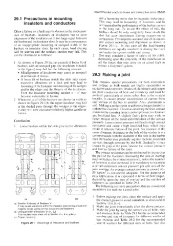
1 As shown in Figure 29.1 (a) as a result of loose fit of all the forces that may arise on an actual fault to
busbars with an unequal gap, the insulators (shaded ensure a foolproof system.
in the figure) may fail for the following reasons:
Misalignment of insulators may cause an unequal
distribution of forces. 29.2 Making a joint
A loose fit of busbars inside the slots may cause
excessive vibrations on a fault and may lead to This requires special precautions for both alurniniuin
loosening of the fasteners and shearing of the wedges and copper, as both metals are highly susceptible to
and/or the edges and the fingers of the insulators. oxidation and corrosion. Oxides of aluminium and copper
Even the insulator mounting section .Y - x' may are poor conductors of heat and electricity and must he
become vulnerable to failure. avoided. particuhrly at joints rather than in the straight
3 When one or all of the busbars are shorter in width as lengths, to ensure proper transmission of current from
shown in Figure 29.l(b) the upper insulator may fail one section of the bus to another. Also, aluminium is
at the shaded parts through the wedges or the edges, soft. Making a perfect joint to achieve a longer durability
as they will now encounter relatively higher cantilever is therefore essential. It involves attaining the least contact
forces. resistance by ensuring proper contact pressure to eliminate
any localized heat. A slightly faulty joint may yield to
faster erosion of the metal and relaxation of the contact
Conclusion pressure. Loose contact pressure will lead to high contact
1 Loose busbars within the slots give rise to vibrations resistance and cause a high localized heat, which may
result in ultimate failure of the joint. For instance. if the
outer diameter, thickness or the hole of the washer is not
commensurate with the diameter of the hole in the busbar
then the washer may gradually sag into the hole, in normal
hood Dnod bond service, through pressure by the bolt. Gradually it may
loosen its grip at the joint, release the contact pressure
and lead to failure of the joint.
The contact resistance can be minimized by increasing
the pull of the fasteners. Increasing the area of overlap
may not reduce the contact resistance. unless the number
of fasteners is also increased. It is mandatory to maintain
a certain minimum contact pressure per unit area of'the
joint overLap. An average contact pressure at around 40-
5.5 kg/cm- IS considered adequate. For the purpose of
easy application, it is expressed in terms of bolt torque.
depending upon the area of overlap and the number of
fasteners, as specified in Table 29.1.
The following are more precautions that are considered
mandatory for making a good joint:
1 Before making the joint, clean the surface and apply
(4 (b) (C) the contact grease to avoid oxidation. as discussed in
(a) Smaller thickness of Busbars 'a' Section 13.6.1(iv).
It may cause vibrations within the insulator slots during a fault and 2 Make the joint immediately after the above process.
magnify forces acting on the insulators and fasteners 3 Make the joint by using the correct size of bolts, nuts
(b) Unequal width of busbars 'b (b,, b2) and washers. Refer to Table 29.1 for the recommended
The insulator may shear off at Section X - X or yoke y
(e) Proper mounting number and size of fasteners for different widths of
bus sections and Table 29.2 for the recommended
Figure 29.1 Mountings of insulators and busbars size of washers for different sizes of bolts. See also