
Page 950 - Industrial Power Engineering and Applications Handbook
P. 950
28/900 Industrial Power Engineering and Applications Handbook
Proximity effect phase along similar lines to those calculated in Example
From Figure 28.1 9(c) conductor effective spacing 28.10 for a reactance of
se = 3JSAB ' SBC ' ScA X, = 0.108 x ~ 50 = 5.40 x 10⁻³ R
1000
SA, = Sac = 302 mm
For the rest of the calculations for mechanical suitability of
and SC, = 2 . SA, = 604 mm the busbar system the procedure for rectangular sections
can be followed.
.'. Se = 3d302 x 302 x 604
= 380.5 mm (C) Tubular sections
and X, from graph of 127 mm channel = 108 Now consider a tubular section for the same requirements.
Choose a tube of size 5" (standard pipe) from Table 30.8
= 0.108 R/1000 m per phase having the following dimensions,
Impedance
For phases
Z= J0.01195z +0.108'
Outside diameter (OD) = 141.30 mm = 2 r,
= 0.108 WOO0 m
Inside diameter (ID) = 128.20 mm = 2 . r2
Voltage drop for 50 m length in phases R and B
A = 2724 mm2
50
1000
= 2500 x 0.108 x ~ Nominal current rating = 3550 A
= 13.5 V For a neutral choose a tube of size 3", having
which is 3.25% for a system voltage of 415 V. The system OD = 88.90 mm
chosen is good up to a length of 50 m. Beyond this the and ID = 77.92 mm
voltage drop may exceed the desirable limits and require
either larger channels or a reduced centre spacing S. Reduced A = 1439 mm2
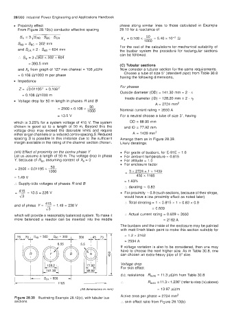
spacing S is possible in this instance due to the sufficient Arrange them as in Figure 28.39.
margin available in the rating of the channel section chosen. Likely deratings:
(viii) Effect of proximity on the centre phase Y For grade of busbars, for E-91 E = 1 .O
Let us assume a length of 50 m. The voltage drop in phase For ambient temperature = 0.815
V, because of Rac, assuming content of X, = 0 For altitude = 1 .O
For enclosure factor
50
1000 - 3 x 2724 + 1 x 1439
= 2500 x 0.01 195 x ~
= 1.49 v 450 x 1165
= 1.83%
:. Supply-side voltages of phases R and 6
:. derating = 0.83
- 415 13.5 = 226 V For proximity = 0.9 (such sections, because of their shape,
& would have a low proximity effect as noted later)
41 5 :. Total derating = 1 x 0.815 x 1 x 0.83 x 0.9
and of phase Y = - 1.49 = 238 V
43 = 0.609
which will provide a reasonably balanced system. To make it :. Actual current rating = 0.609 x 3550
more balanced a reactor can be inserted into the middle = 2162 A
The busbars and the inside of the enclosure may be painted
with matt finish black paint to make this section suitable for
= 1.2 x 2162
= 2594 A
If voltage variation is also to be considered, then one may
have to choose the next higher size. As in Table 30.8, one
can choose an extra-heavy pipe of 5" size.
L - For skin effect:
Voltage drop
d.c. resistance ffdc20 = 11.3 pWm from Table 30.8
I
=
1165
= 13.97 pQ/m
(A// dimensions m mm) .. RdCa5 11.3 x 1.236' (refer to step (iv) above)
Active area per phase = 2724 rnm2
Figure 28.39 Illustrating Example 28.12(c), with tubular bus
sections :. skin effect ratio from Figure 28.13(b)