Page 952 - Industrial Power Engineering and Applications Handbook
P. 952
28/902 Industrial Power Engineering and Applications Handbook
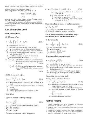
       Effect of proximity  on the centre phase  Y    Rdc at 85°C = Rdc20  [1 + az"(62 - e,)]   (28.6)
       The voltage drop in this phase, assuming X,  = 0
                                                            azo = temperature  coefficient  of  resistance  at
                        = 2500 x 0.01397 x 50                    20°C per "C
                                       1000                RdcZo = d.c. resistance at 20°C
                        = 1.75 v                             13~ operating temperature = 85°C
                                                               =
       which  is  only 0.4% of  the system voltage. This bus system   O1 = since the value of R,,  is available at 20°C
       will  thus provide a near-balanced system.                therefore,  01 = 20°C
         For the rest of the calculations for the mechanical suitability
       of  a  busbar  system the procedure  for  rectangular sections   Proximity effect in terms of busbar reactance
       can be followed.
                                                      s, = (Sa ' s, ' sy3                   (28.7)
       List of formulae used                          S, = effective or geometric mean spacing
                                                      Sa, Sb, and S, = spacing between conductors
       Short-circuit effects
                                                      Use of saturable reactor to balance a large
       (1) Thermal effects                            unbalanced power distribution system
                                                      To determine size
            l;o
          -
        e---.  (2 - )* . (1 + a,,0). t        (28.1)
                                                                                            (28.8)
         0, = temperature rise in "C
         I,,  = symmetrical fault current r.m.s.  in Amp   Xp = lost reactance of  Y phase
         A  = cross-sectional area of the conductor in mm2   L = inductance of Xp
           = temperature coefficient of resistance at 20"C/"C   I, = current in R or B phase
          6 = operating temperature of the conductor at which   IY = current in Y phase
             the fault occurs in "C
         K =  1.166 for aluminium and 0.52 for copper   Reluctance of the magnetic path
          t = duration of fault in seconds
        or   x & = 0.0799 for aluminium for an operating
           A                                                                                (28.9)
                    temperature at 85°C and end temperature
                    at 185°C                  (28.2)   I,  = length of the air gap in metres
            I,, JI = 0.12 for copper for an operating tempera-   po = permeability of  air (free space) = 4n.   H/m
             A      ture  at  85°C and end a  temperature  at   = relative permeability  of the silicon steel used for
                    185°C                                  the laminates in H/m
                                              (28.3)    A = area of cross-section of core in square metres
                                                        k  = total  length of the magnetic circuit in metres
        (2) Electrodynamic effects
                                                      Calculating stresses on a fault
               16.1;
                     x  104  N/m
        F,,  = k. -                           (28.4)   Bending stress on busbars at section
                 S                                             F,  . I
        F,  = maximum dynamic force that may develop on  a   x -x=  12,M.N  = kg/cm         (28.10)
             fault                                       F,  = maximum electrodynamic forces acting on each
         I,,  = r.m.s.  value  of  the  symmetrical  fault  current  in   support in the event of a fault
             Amps                                          1 = centre distance between two busbar supports
          k  = space factor                               M  = sectional  modulus  of  each  busbar  at  section
         S = centre spacing between two phases in mm         x-x
                                                              1
        Skin effect                                         = -a. b2 in cm3
                                                              6
                                                          N  = number of busbars per phase
        Effect on current-carrying capacity
                                                      Further reading
        I,,  = I,,   '                        (28.5)
                                                       1  ERDA,  'Study  on  feasibility  of  upgrading  the  operating
         I,,  = permissible current capacity of the system   temperature  of  AI busbars without plating'.
        Rdc = d.c. resistance                         2  Golding,  E.W.,  Electrical  Measurements  and  Measuring
        R,,  = a.c. resistance                           Instruments.
        Id,  = d.c. current                           3  Lynthall, R.T., The J & P Switchgear Book. Buttenvorth, London.
                                                      4  Thomas, A.G. and Rata, P.J.H., Aluminium Busbar. Hutchinson
        Conductor resistance at higher temperature       Scientific and Technical for Alcan Industries Ltd.

