
Page 948 - Industrial Power Engineering and Applications Handbook
P. 948
28/898 Industrial Power Engineering and Applications Handbook
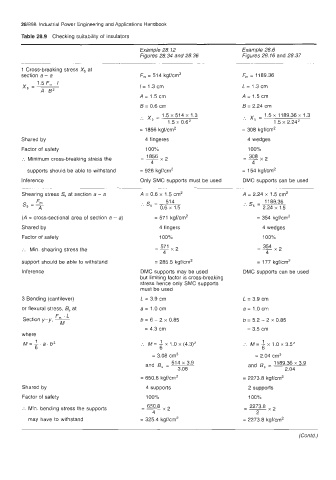
Table 28.9 Checking suitability of insulators
Example 28.12 Example 28.6
Figures 28.34 and 28.36 Figures 28.16 and 28.37
1 Cross-breaking stress X, at
section a - a F,, = 51 4 kgflcm' F,, = 1189.36
1.5 F, . I
Xb =- I= 1.3 cm L = 1.3 cm
A.5'
A = 1.5 cm A = 1.5 cm
B = 0.6 cm B = 2.24 cm
.
x, = 1.5 x 514 x 1.3 '. - 1.5 x 11 89.36 x 1.3
1.5 x 0.6' b - 1.5 x 2.24'
= 1856 kgflcm' = 308 kgflcm2
Shared by 4 fingeres 4 wedges
Factor of safety 100% 100%
:. Minimum cross-breaking stress the - 1856 =mx2
4 4
supports should be able to withstand = 928 kgflcm' = 154 kgf/cm2
Inference Only SMC supports must be used DMC supports can be used
.~
~~
~~
Shearing stress S, at section a - a A = 0.6 x 1.5 cm2 A = 2.24 x 1.5 cm2
s, = 5 514 1189.36
A :. s, = ~ 0.6 x 1.5 :. s, = ~ 2.24 x 1.5
(A = cross-sectional area of section a - a) = 571 kgflcm2 = 354 kgflcrn'
Shared by 4 fingers 4 wedges
Factor of safety 100% 1000/0
-- 571 x 2
:. Min. shearing stress the - =Ex2
4 4
support should be able to withstand = 285.5 kgWcm' = 177 kgfhm'
Inference DMC supports may be used DMC supports can be used
but limiting factor is cross-breaking
stress hence only SMC supports
must be used
3 Bending (cantilever) L = 3.9 cm L = 3.9 cm
or flexural stress, 6, at a = 1 .O cm a = 1.0 cm
F, . L
Section y-y, ~ b = 6 - 2 x 0.85 b = 5.2 - 2 x 0.85
M
= 4.3 cm = 3.5 cm
where
a.
M= 1. b2 :. M = 1 1 .o x (4.3)Z :. M = 1 1.0 x 3.52
x
x
6 6 6
= 3.08 cm3 = 2.04 cm3
514 x 3.9 and - 1189.36 x 3.9
3.08 2.04
and B, = ~ s-
= 650.8 kgflcm' = 2273.8 kgf/cm2
Shared by 4 supports 2 supports
Factor of safety 100% 100%
2273.8
:. Min. bending stress the supports - 650.8 --
--
4 2
may have to withstand = 325.4 kgflcm2 = 2273.8 kgf/cm2
(Contd.)