
Page 949 - Industrial Power Engineering and Applications Handbook
P. 949
Carrying power through metal-enclosed bus systems 28/899
Table 28.9 Contd.
Example 28.72 Example 28.6
Figures 28.34 and 28.36 Figures 28.76 and 28.37
Inference DMC supports may be acceptable SMC supports alone must be
but limiting factors is cross- used with a modified design,
breaking stress, at to withstand a higher bending
location a - a. Hence only SMC stress or the design of the
supports must be used bus system itself be modified
as mentioned below under
note 3
Conclusion In this particular instance, section In this case, section y - y at the
a - a at the fingers is more bolt mounting holes is more
vulnerable. If the supports vulnerable If the supports
fail, they may fail from here. fail, they may fail from here
~~ -~~
~~
Notes
Factor of safety
It is possible that during the fault only one of the insulators is subject to the transitory first peak of the fault, as there may be slight
misalignment between the insulators, asymmetry in the busbars, an imperfect bolt fixing and their fastening, or a combination of such factors.
To be on the safe side it is advisable to consider each support and its fasteners to be suitable to withstand the forces by themselves We have
assumed a factor of safety of 100% in all the above calculations to account for this.
F,,, for all particular fault levels remains the same, irrespective of the current rating of the system (equation (28.4). A low current system
employs fewer and smaller busbars and is supported on less and smaller supports and hardware. Such a system therefore may have to
withstand much higher stresses than a higher current-carrying system and is more likely to yield to such stresses unless adequate measures
are taken while selecting the size of supporting hardware or spacing (t) between the adjacent horizontal supports.
When a component supporting the current-carrying system is likely to be subject to severe stresses, and its own stress-bearing capacity may
be marginal as in Example 28.6, it is advisable to take a higher size of such a component in its thickness or diameter or a better quality
material. It is also possible to mitigate the stresses by reducing the distance between the two mounting supports of the same phase (i to be
<400 mm). In the above case we have assumed this as 400 mm. If the centre spacing S between the two phases can be raised conveniently.
it can also reduce the severity of F,
Derating due to proximity = minimum 0.80
:_ Total derating = 1 x 0.815 x 1 x 0.8 x 1 x 0.80
= 0.5216
:. Actual current rating of channels = 0.5216 x 5440
= 2837.5 A
which is good for the required rating. The conductors have
enough margin for higher load demands which may arise
- LS=302 +S=3024 due to a voltage drop of up to -10% of the rated voltage if
1125 --A
most of the loads are industrial drives.
\\
\ Aluminium Voltage drop
frame (All dimensions in mm) Skin effect
d.c. resistance for one channel (Table 30.9)
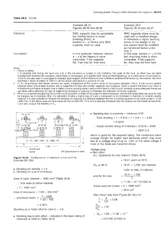
Figure 28.38 Configuration of channels in box form for
Example 28 12(b) = 18.41 @/m at 20°C
Rd, at 85°C = 18.41 x 1.236' per channel
Derating for altitude = 1 .O (refer to step (iv) above)
Derating for size of enclosure;
- 18.41 x 1.236
and for the box
Area of each channel = 1695 mm2 (Table 30.9) 2
m
= 11.38 x 10-~ ~~1000
:. Total area of active material
Active area per phase = 2 x 1695 mm2
= 7 x 1695 mm2
= 33.9 cm2
Area of enclosure = 1125 x 450 mrn2
Skin effect ratio from Figure 28.13(c) for
7 x 1695
:. enclosure factor =
1125 x 450
= 2.34%
= 1.05
Derating as in Table 28.6 for item 2 = 0.8 RdC
:. R,, = 1.05 x 11.38 x 1 0-3
Derating due to skin effect - included in the basic rating of
channels at 5440 A (Table 30.9) = 0.01195 RilOOO m