
Page 946 - Industrial Power Engineering and Applications Handbook
P. 946
28/896 Industrial Power Engineering and Applications Handbook
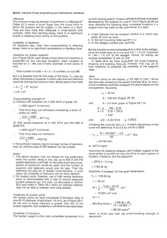
Jnference current-carrying system. It has to withstand all kinds of stresses
The minimum shearing strength of aluminium is 1650 kg/crn2 developed by the busbars on a fault. From Figure 28.36 we
(Table 30.1) which is much larger than the actual force to have identified the following likely vulnerable locations in a
which the busbars will be subject, in the event of a fault. support that may yield on the occurrence of a fault;
They are thus more than adequate in cross-section and
numbers. Other than bending stress, there is no significant Finger between the two busbars, section a-a, which may
tensile or shearing force acting on the busbars. shear off from its roots.
At the bolt mounting holes section y-y.
Suitability of fasteners At the wedges marked with hatching.
On fasteners also, other than cross-breaking or shearing
stress, there is no significant compressive or bending force.
But the insulator is more vulnerable at a-a, than at the wedges,
since the shear area at a-a is only 0.6 x 1.5 cm2 compared
Fasteners for busbar supports to 1.98 x 1.5 cm2 at the wedges. Hence, for brevity, we
As in Figure 28.34, each phase of four aluminium sections is analyse possibilities (i) and (ii) only.
supported on four two-way insulators. Each insulator is In Table 28.9 we have evaluated the cross-breaking,
mounted on 2 x M8 size of bolts (diameter of bolt shank, 8 shearing and bending (flexural) stresses, that may act at
mm). such locations, to establish the suitability of the supports
used.
:. Total number of bolts = 4 x 2 = 8 numbers of size M8
But it is possible that the first peak of the force, Fm, may act Note
either downwards or upwards. In which case only four fasteners For more clarity on the subject, in the light of note 1 above
would be sharing the force at a time. Stress area of four bolts we have also worked out the earlier Example 28.6, for short-
circuit conditions and then analysed the above details for this
= 4 x x 8' sq.mm arrangement. Assuming
4
= 2.01 cm2 lSc = 45 kA
Cross-breaking strength of S= 100 rnm (Figure 28.16)
(i) Ordinary MS fasteners as in IS0 4016 of grade 4.6,
and K= 0.9 from graph of Figure 28.7 for
= 2200 kg/cm2 (minimum)
100-6.35
:. Total force they can withstand considering a factor of -- S-a 6.35+101.6
a+b
safety as 100%
= 0.87
and alb = 6.351101.6 Le. 0.0625
(ii) High tensile fasteners as in IS0 4014 and IS0 898 of
grade 8.8, Choosing the curve for db = 0.1. A slight interpolation in this
curve will determine K as 0.9 for a/b as 0.0625
= 4400 kg/cm' (minimum)
:. Total force they can withstand .'. F, = 16 x (45000)2 x 0.9 x lod N/m
100
= 29 160 N/m
In this particular instance, due to the large number of fasteners,
even an ordinary type of MS fastener will be suitable. or 2973.4 kglm
Assuming the distance between each busbar support of the
Notes same phase to be 400 mm then the force on each section of
1 The above situation may not always be true particularly busbars, insulators and the fasteners.
when the current rating is low, say up to 600 A and the
system fault level is still high. In this case much less cross- = 2973.4 x 0.4 kg
section of aluminium would be used, and the number of
supports and fasteners would also be less. Then the = 1189.36 kg
fasteners will also be of smaller cross-sections. In such Suitability of busbars; for the given parameters:
cases the suitability of fasteners will be more relevant.
2 For busbar joints, however, use of high tensile fasteners F,,, = 1189.36 kg
alone is recommended with a view to ensure adequate
contact pressure per unit area, as discussed in Section t = 40 cm
29.2 and noted in Table 29.1 which an ordinary fastener
may not be able to maintain over long periods. = 1 6.35 x 101.6' cm3
6 1000
= 10.925 cm3 and
Fasteners for busbar joints
For busbar joints we have considered 8 Numbers bolts of N= 1
size M-10 (diameter of bolt shank, 10 mm), as in Figure 29.4.
As the size of these fasteners is greater than that of the :. Sending stress = 1 189.36 x 40
busbar supports, their suitability is not determined separately. 12 x 10.925 x 1
= 362.89 kg/cm2
Suitability of insulators which is much less than the cross-breaking strength of
The busbar support is the most vulnerable component in a aluminium.