Page 941 - Industrial Power Engineering and Applications Handbook
P. 941

Carrying power through metal-enclosed bus systems  28/891
        28.9  Sample calculations for                  Continuous current  rating            2500 A
              designing a 2500 A non-isolated          Ambient  temperature                   50°C
                                                                                              85°C
                                                       Maximum permissible operating temperature
              phase aluminium busbar system            Permissible final temperature at the end of the
                                                       fault                                 185°C
        Example 28.12
        Design parameters                              (A)  Rectangular sections
        Supply system three-phase four-wire 415 V  ? IO%,
                                           50 HZ ? 3%   (i) Minimum size of busbars for short-circuit conditions
        Fault level                            45 kA   The  minimum size of  busbars for an operating temperature
        Duration of fault                    1 second   of 85°C and a final temperature of  185°C can be ascertained
                                                       from the curves of  Figure 28.5,  suggesting
                            870                        r. 4 = 0.0799
                                                       A
         f                                             or   A=-.  45   4i
                                                              0.0799
          1
                                                            = 563.2 sq. mm
                                                       Maximum temperature rise of the busbars at the rated current
                                                         = 85 - 50
                                                         = 35°C
                                                       Assume the temperature of the busbars at the time of fault =
                                                       85°C and rectangular flats of electrolytic  grade E-91 E or its
                                    Insulator supporting   equivalent.  Busbars chosen for  each  phase - four  (152.4
                                                       mm x  6.35 mm) - which  are more than  the  minimum size
                                   MS or aluminium     required to  account  for  the  thermal effects  during a  short
                                   enclosure           circuit  condition
        (All dimensions in mm )
                                                       for  neutral -two  (52.4 mm x 6.35 mm)
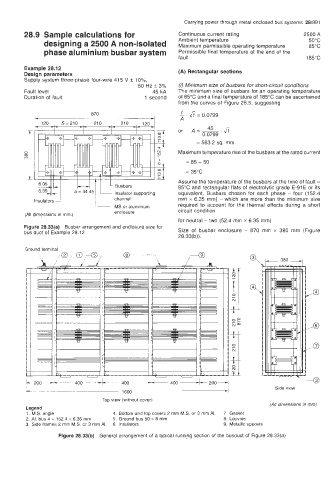
        Figure 28.33(a)  Busbar arrangement and enclosure size for
        bus duct of  ExamDle 28 12                     Size  of  busbar  enclosure  - 870  mm  x  380  mm  (Figure
                                                       28.33(b))
        Ground terminal


                                                                                    Side view

                                Top view (without cover)
                                                                                  (All dimensions in mm)
         Legend
         1.  M.S. anqle            4.  Bottom and top covers 2 mm M.S. or  3 mm AI.   7. Gasket
         2.  AI.  bus i 152.4 x 6.35 mm   5.  Ground bus 50 x 6 mm   8. Louvres
                x
         3.  Side frames 2 mm M.S. or 3 mm AI.   6.  Insulators     9.  Metallic spacers
                  Figure 28.33(b)  General arrangement of  a typical running section of  the busduct of  Figure 28.33(a)
   936   937   938   939   940   941   942   943   944   945   946