
Page 940 - Industrial Power Engineering and Applications Handbook
P. 940
28/890 Industrial Power Engineering and Applications Handbook
physical location so that each phase is under an equally
inductive effect produced by the other two phases. The
arrangement is illustrated in Figure 28.31 This can be
performed by arranging a straight length of a bus into
three equal sections (or in multiples of three), as shown.
If x is the reactance of phases R and B, and y that of
phase Y in the first section, then phases B and Y will have
reactance x and R a reactance y in the second section. In
the third section, phases Y and R will have a reactance of
x each and phase B will have a reactance y. Hence, the
reactance of each phase, at the end of the three lengths,
will be balanced at (2x + y), causing equal load sharing MS cover \
and an equal voltage drop in all three phases. This
arrangement would thus make the system almost balanced 0000000
inductively by each phase having equal exposure to the Magnetic
inductive fields produced by the other two phases. Due loops oc300o0
to inductive balancing, the transposition equalizes the Each loop
reactances in each phase and improves the current sharing causes 000000
by all the three phases, besides an equal voltage drop magnetic F oooooooo
through the length of the bus. loss
However, there may not be an appreciable improvement
in the proximity effect between each section, unless the (a) Breaking of electrical paths do not diminish the magnetic field
transpositions are increased infinitely, as in the case of a Aluminium top and
stranded three-phase cable which has continuously twisted bottom covers
conductors and represents an ideal transposition. In \
addition, there is no change in the skin effect. This
arrangement therefore has the purpose primarily of MS side -
achieving an inductively balanced system and hence a
balanced sharing of load and equal phase voltages at the covers
far end.
It is also cumbersome to arrange a bus system with
phase transposition. This technique has therefore not found
many applications in a bus system. It is more useful in
dealing with inductive interference in communication ,
lines (Section 23.5.2(C)). I I
(b) An economical and low loss enclosure
4 Changing the configuration of busbars
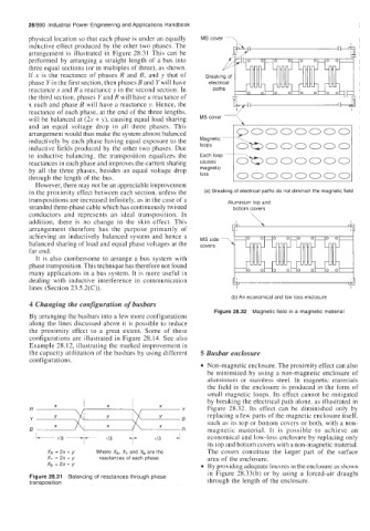
Figure 28.32 Magnetic field in a magnetic material
By arranging the busbars into a few more configurations
along the lines discussed above it is possible to reduce
the proximity effect to a great extent. Some of these
configurations are illustrated in Figure 28.14. See also
Example 28.12, illustrating the marked improvement in
the capacity utilization of the busbars by using different 5 Busbar enclosure
configurations.
Non-magnetic enclosure. The proximity effect can also
be minimized by using a non-magnetic enclosure of
aluminium 01- stainless steel. In magnetic materials
the field in the enclosure is produced in the form of
small magnetic loops. Its effect cannot be mitigated
by breaking the electrical path alone, as illustrated in
X X X
R Y Figure 28.32. Its effect can be diminished only by
Y Y Y Y B replacing a few parts of the magnetic enclosure itself,
such as its top or bottom covers or both, with a non-
X X X R magnetic material. It is possible to achieve an
+ 7 (/3 4 economical and low-loss enclosure by replacing only
1'
1/3
1/3
~
The covers constitute the larger part of the surface
&=2x+y Where X,, X, and XB are the its top and bottom covers with a non-magnetic material.
xy =2x+y reactances of each phase area of the enclosure.
x, =2x+y By providing adequate louvres in the enclosure as shown
in Figure 28.33(b) or by using a forced-air draught
Figure 28.31 Balancing of reactances through phase
transposition through the length of the enclosure.