
Page 939 - Industrial Power Engineering and Applications Handbook
P. 939
Carrying power through metal-enclosed bus systems 281889
For instance, a bus system with 4 x 152.4 x 6.35 mm
conductors may be arranged into two groups of two :. ~ Ra, from the graph in Figure 28.1 3 (a) by interpolation for
R dC
conductors each, according to Figure 28.29(b). Then the an EIE-M grade of aluminium = 1.1 3
improved rating of this system as in Table 30.4 will be
Rdc = 0.056 Q/lOOO m per conductor
= 2 x 2860
= 5720 A = 0.056/4 R/1000 m for 4 conductors
0.056
as against :. R,, = 1.13 x -
4
= 0.0158 R/1000 m
4240 A for all conductors put together as in Figure
28.331a) or :. Impedance Z = 1/0.0158' + 0.045'
1.18 x 4240, i.e. 5003 A when arranged as in
arrangement 2 of Figure 28.14. = 0.0477 R/1000 m
Thus. in phase interleaving, there will be better utilization Voltage drop
of conductor capacity by 5720/5003 or >14% over Accordingly the revised voltage drop for 40 m of bus length
arrangement 2 in Figure 28.14. 40
= 2000 x 0.0477 x ~
1000
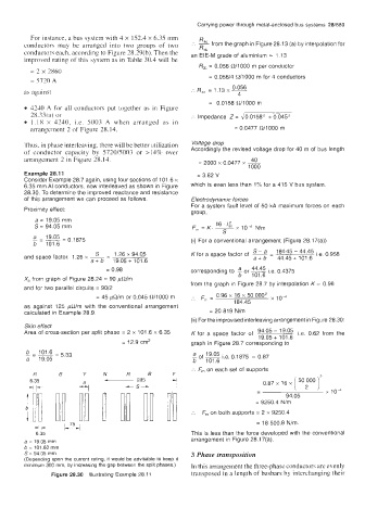
Example 28.1 1 = 3.82 V
Consider Example 28.7 again, using four sections of 101.6 x
6.35 mm AI conductors, now interleaved as shown in Figure which is even less than 1% for a 415 V bus system
28.30. To determine the improved reactance and resistance
of this arrangement we can proceed as follows. Electrodynamic forces
For a system fault level of 50 kA maximum forces on each
Proximity effect:
group,
a = 19.05 mm
S = 94.05 mm
(i) For a conventional arrangement (Figure 28.17(a))
S - 1.26 x 94.05
and space factor, 1.26 x - Kfor a space factor of S-a - 184'45 - 44.45 i.e. 0.958
44.45 + 101.6
-
a + b
a+ b 19.05+ 101.6
= 0.98 corresponding to a or - 0.4375
i.e.
44.45
X, from graph of Figure 28.24 = 90 pWm b 101.6
and for two parallel circuits = 90/2 from the graph in Figure 28.7 by interpolation K = 0.96
- 0.96 x 16 x 50000'
= 45 pR/m or 0.045 R/1000 m . rn - 10-4
" 184.45
as against 125 @/m with the conventional arrangement
calculated in Example 28.9. = 20 819 N/m
(ii) For the improvised interleaving arrangement in Figure 28.30:
Skin effect
Area of cross-section per split phase = 2 x 101.6 x 6.35 K for a space factor of 94.05 - 19.05 i.e. 0.62 from the
19.05 + 101.6
= 12.9 cm2 graph in Figure 28.7 corresponding to
b 101.6
- = - 5.33.
=
a 19.05 a of 19.05 i.e. 0.1875 = 0.87
101.6
b
:. F, on each set of supports
R B
6.35 0.87 x 16 x [ 502000 )*
+ p-
- x lo4
94.05
= 9250.4 Nlm
:. F,, on both supports = 2 x 9250.4
= 18 500.8 Nim.
6.35 This is less than the force developed with the conventional
a = 19.05 mm arrangement in Figure 28.17(a).
b = 101.60 mm
S = 94.05 mm 3 Phase transposition
(Depending upon the current rating, it would be advisable to keep it
minimum 300 mm, by increasing the gap between the split phases.) In this arrangement the three-phase conductors are evenly
Figure 28.30 Illustrating Example 28.1 1 transposed in a length of busbars by interchanging their