
Page 936 - Industrial Power Engineering and Applications Handbook
P. 936
28/886 Industrial Power Engineering and Applications Handbook
Length = k
f$-- Air gap
I 'tg' = 2 mrn
i
I
--c 1
6.35
7
I I
I I
I I
I
f t
I
I I
I I
I I I+
I I
I I 6.35
I I 1 I
2 1
Min 250 mm 4 Min 250 mm
200
Depth d = 500
Magnetic field sfrength 'H' (Ah) --+
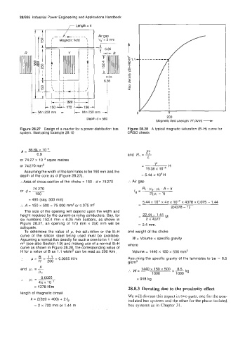
Figure 28.27 Design of a reactor for a power distribution bus Figure 28.28 A typical magnetic saturation (B-H) curve for
system. Illustrating Example 28.10 CRGO sheets
66.84 x 1 0-3
A= z:
0.9 and R, = -
or 74.27 x squre metres L
or 74270 mm2 - 12 H
18.38 x lo4
Assuming the width of the laminates to be 150 mm and the
depth of the core as d (Figure 28.27), = 5.44 x 10⁴~
:.Area of cross-section of the choke = 150 . d = 74270 :. Air gap
74 270 R1 .pr .A- k
or d=- I, =
150 2(Pr - 1)
= 495 (say, 500 mm) 5.44 x lo4 x 4n x lo-' x 4378 x 0.075 - 1.44
:. A = 150 x 500 = 75 000 mm2 or 0.075 m2 -
2(4378 - 1)
The size of the opening will depend upon the width and
height required by the current-carrying conductors. Say, for - 22.44 - 1.44 M
six numbers 152.4 mm x 6.35 mm busbars, as shown in 2 x 4377
Figure 28.27, an opening of 170 mm x 250 mm will be = 2.4 mm.
adequate.
To determine the value of p, the saturation or the B-H and weight of the choke
curve of the silicon steel being used must be available.
Assuming a normal flux density for such a core to be 1 .I wb/ W = Volume x specific gravity
m2 (see also Section 1.9) and making use of a normal 8-H where
curve as shown in Figure 28.28, the corresponding value of
H for a value of B as 1.1 wb/m' can be read as 200 Nm, Volume = 1440 x 150 x 500 mm3
. p,=B=l.l= 0.0055 H/m Assuming the specific gravity of the laminates to be = 8.5
H
200
g/cm3
P
and pr = - 1440 x 150 x 500
1000
10 :. w = 1000 8.5 kg
:. pr= 0.0055 = 918 kg
4nx 10-7
= 4378 H/m
28.8.3 Derating due to the proximity effect
length of magnetic circuit
We will discuss this aspect in two parts, one for the non-
k = 2(320 + 400) + 2./g isolated bus systems and the other for the phase-isolated
= 2 x 720 mm or 1.44 m bus systems as in Chapter 3 1.