
Page 932 - Industrial Power Engineering and Applications Handbook
P. 932
28/882 Industrial Power Engineering and Applications Handbook
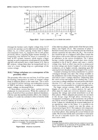
Figure 28.21 Graph to determine 0, of a tubular bus section
(through the busbars) and a higher voltage drop. In LT of the other two phases, which would offset their proximity
systems the spacings can be adjusted only marginally to effects (see Figure 28.22). The conductor of phase Y
reduce X,, as a lower spacing would mean a higher therefore would carry no distortion beyond the distortion
electrodynamic force, F, (equation (28.4)) and greater already caused by the skin effect (Rac/Rdc). The result of
proximity effects, requiring higher busbar deratings. A this would be that in a balanced three-phase system the
compromise may therefore be drawn to economize on three phases will assume different impedances and cause
both. In HT systems, however, which require a larger an unbalance in the current distribution. The Y phase
spacing, no such compromise would generally be possible having a smaller impedance, would share more current
and they will normally have a high content of X,. But in compared to the R and B phases and cause a smaller
HT systems, voltage drop plays an insignificant role in voltage drop. Such an effect may not be as pronounced
view of a lower voltage drop as a percentage of the in lower ratings and shorter lengths of current-carrying
system voltage. conductors, as on higher currents, depending upon the
spacing between the phases and the length of the system.
28.8.2 Voltage unbalance as a consequence of the Consider a feeding line from a transformer to a power
proximity effect switchgear through a bus duct. The voltage available at
the distribution end of this feeding line may be unequal
The proximity effect does not end here. It still has some and tend to cause a voltage unbalance. Depending upon
far-reaching consequences in terms of unequal voltage the rated current and length of the feeding line, it may
drops in different phases at the same time. This is more even cause a voltage unbalance beyond permissible limits
so on large LT current-carrying, non-isolated bus systems (Section 12.2) and render the system unstable and in
of 2000 A and above, resulting in an unbalance in the some cases even unsuitable for an industrial application.
supply voltage, as discussed below. For larger current systems, 2000 A and above and
A three-phase system has three current-carrying lengths of over 50 m, a correct analysis for such an
conductors in close proximity. While the conductors of effect must be made and corrective measures taken to
phases R and B will have an almost identical impedance, equalize the voltage and current distribution in all the
with the same skin and the proximity effects, the conductor three phases. Where adequate precautions are not taken
of phase Y is under the cumulative effect of electric fields at the design stage through phase interleaving or
transposition techniques, as discussed later, the problem
can still be solved by making up for the lost inductance
R Y B
in the Y phase by introducing an external inductance of
an appropriate value in this phase. It is possible to do
this by introducing a reactor core into this phase, as
illustrated in Figure 28.23. This inductor will compensate
for the deficient inductance and equalize the impedances
in all three phases, thus making the system balanced and
stable. We illustrate briefly later a procedure to determine
t the size of a saturable reactor core, when required, to
meet such a need.
Influence of electric fields of conductors Rand B is
offset in a 3-4 system. The proximity effect in phase Y Example 28.8
therefore gets nullified Consider Example 28.6 to determine the content of proximity;
(i) For reactance X, on account of the proximity effect, use
Figure 28.22 Influence of proximity Figure 28.16 and the graph of Figure 28.24: