
Page 927 - Industrial Power Engineering and Applications Handbook
P. 927
Carrying power through metal-enclosed bus systems 28/877
of metal, particularly in larger sections. While larger
sections would be imperative for such large ratings, their
own rating would fall to a low of 14-1 8% of their normal
current capacity. (See Table 30.5 for larger sections,
providing current ratings up to six bars in parallel.) In
such cases it is advisable to arrange the bars in any other
convenient configuration than in parallel, as illustrated
in Figure 28.14 or to use round or channel sections to
achieve better results and a higher level of metal utilization. CL <q
28.7.2 Determining the skin effect
As a result of the electric field around the conductors the
frequency of the system has a very significant bearing
on the skin effect. The various curves as established
through experiments and, as reproduced in Figures 28.13 -___-
(a), (b) and (c) respectively for rectangular tubular and Tube reducer Tube for flat connection
channel conductors, are thus drawn on the ,/m basis.
At 50 Hz, the value of the skin effect, RaclRac, can be (a) For a tubular section
read directly from these curves, as the curves for different
cross-sectional areas and conductivity, at 50 Hz, have
also been drawn in the lower part of the figure.
Ratings of up to 3200 A are normally required for r;
distribution purposes such as for interconnecting a ii li
distribution transformer to a PCC, or a large PCC to 'i ii
another large PCC in a sub-station. Common practice
for making such connections is to use rectangular cross-
sections, which are easy to handle, manoeuvre and make i
joints, compared to a channel or a tubular section. Channel i
and tubular sections require special tools and skilled ii
workers, particularly when bending or making joints and
end terminations. However, suitable fittings and fixtures, ii
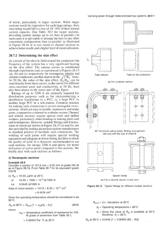
some of which are shown in Figure 28.15 (a) and (b), are ii 1
also provided by leading aluminium section manufacturers
as standard practice to facilitate such connections. The 90" Horizontal splice plates. Bolting arrangement
welding of such joints will require special welding will vary with the size of channel
equipment and adequate in-house testing facilities to check
the quality of weld. It is, however, recommended to use
such sections, for ratings 3200 A and above, for better
utilization of active metal compared to flat sections. We
briefly deal with such sections as follows. -
(i) Rectangular sections I I I I
Example 28.6 I I
Consider a section of 101.6 mm x 6.35 mm of grade EIE-M
as in Figure 28.16. From Table 30.7 for its equivalent grade
CIS-M
(i) Rdc = 44.55 mlm at 20°C Spacer clamp
or 44.55 x 1 000 x 1 O~ R/I 000 m (b) For a channel section in box form
Le. 0.0445 R/lOOO m
Figure 28.15 Typical fittings for different busbar sections
Area of cross-section = 101.6 x 6.35 x cm2
= 6.4516 cm2
Since the operating temperature should be considered to be
85"C,
RdC2O = d.c. resistance at 20°C
Rd, at 85°C = Rd@o [1 + azo(& - e,)] (28.6)
0, = Operating temperature = 85°C
where
= temperature coefficient of resistance for CIS- e, = Since the value of Rdc is available at 20°C
M grade of aluminium from Table 30.1, therefore, 0, = 20°C.
= 0.00403 Per "C at 20°C Rd, at 85°C = 0.0445 [1 + 0.00403 (85 - 20)]