
Page 922 - Industrial Power Engineering and Applications Handbook
P. 922
28/872 Industrial Power Engineering and Applications Handbook
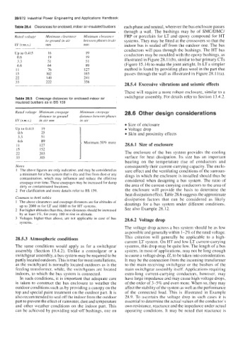
Table 28.4 Clearances for enclosed, indoor air-insulated busbars each phase and neutral, wherever the bus enclosure passes
through a wall. The bushings may be of SMC/DMC/
Rated voltage Minimum clearance Minimum c1prrranr.r FRP or porcelain for LT and epoxy compound for HT
to ground in air between phases in uir systems. They may be fitted at the crossovers so that the
kV (Km.s.) mni mm indoor bus is sealed off from the outdoor one. The bus
conductors will pass through the bushings. The HT bus
Up to 0.415 16 19 conductors may be moulded with the epoxy bushings, as
0.6 19 19
3.3 51 51 illustrated in Figure 28.1 l(b), similar to bar primary CTs
6.6 64 89 (Figure 15.14) to make the joint airtight. In LT a simpler
11 76 121 method is found by providing glass wool in the part that
15 102 165 passes through the wall as illustrated in Figure 28.1 l(a).
22 140 24 1
33 222 356
28.5.4 Excessive vibrations and seismic effects
These will require a more robust enclosure, similar to a
Table 28.5 Creepage distances for enclosed indoor ail switchgear assembly. For details refer to Section 13.4.2.
insulated busbars as in BS 159
Ruted voltage Minimum creepage Minimum creepage 28.6 Other design considerations
distance to ground di.mnce between phases
kV (rm,s.) in air mm in uir Size of enclosure
Up to 0.415 19 Voltage drop
0.6 25 1 Skin and proximity effects
3.3 51
6.6 89 Minimum 50% more
11 121 28.6.1 Size of enclosure
15 152
22 203 I The enclosure of the bus system provides the cooling
33 305 surface for heat dissipation. Its size has an important
~. ~ bearing on the temperature rise of conductors and
Notes consequently their current-carrying capacity. The enclo-
I The above figures are only indicative, and may be considered as sure effect and the ventilating conditions of the surroun-
a minimum for a bus system that is dry and free from dust or any dings in which the enclosure is installed should thus be
contamination, which may influence and reduce the effective considered when designing a bus system. The ratio of
creepage over time. These creepages may be increased for damp
dirty or contaminated locations. the area of the current-carrying conductors to the area of
2 For clarification and more details refer to BS 159. the enclosure will provide the basis to determine the
heat dissipation effect. Table 28.6 suggests the approximate
Common to both tables dissipation factors that can be considered as likely
1 The above clearances and creepage distances are for altitudes of deratings for a bus system under different conditions.
up to 2000 m for LT and 1000 m for HT systems.
2 For higher altitudes than this, these distances should be increased See also Example 28.12.
by at least 1%. for every 100 m rise in altitude.
3 Voltages higher .than above, are not applicable in case of bus 28.6.2 Voltage drop
systems.
The voltage drop across a bus system should be as low
as possible and generally within 1-2% of the rated voltage.
28.5.3 Atmospheric conditions This criterion will generally be applicable to a high-
current LT system. On HT and low LT current-carrying
The same conditions would apply as for a switchgear systems, this drop may be quite low. The length of a bus
assembly (Section 13.4.2). Unlike a controlgear or a system, in most of applications, may not be long enough
switchgear assembly, a bus system may be required to be to cause a voltage drop, IZ, to be taken into consideration.
partly located outdoors. This is true for most installations, It may be the connection from the incoming transformer
as the switchyard is normally located outdoors as is the to the main receiving switchgear or the busbars of the
feeding transformer, while, the switchgears are located main switchgear assembly itself. Applications requiring
indoors, to which the bus system is connected. extra-long current-carrying conductors, however, may
In such conditions, it is important that adequate care have large impedance and may cause high voltage drops,
is taken to construct the bus enclosure to weather the of the order of 3-5% and even more. When so, they may
outdoor conditions such as by providing a canopy on the affect the stability of the system as well as the performance
top and special paint treatment on the outdoor part. It is of the connected load. This is illustrated in Example
also recommended to seal off the indoor from the outdoor 28.9. To ascertain the voltage drop in such cases it is
part to prevent the effect of rainwater, dust and temperature essential to determine the actual values of the conductor’s
and other weather conditions on the indoor part. This own resistance, reactance and the impedance under actual
can be achieved by providing seal-off bushings, one on operating conditions. It may be noted that reactance is