
Page 924 - Industrial Power Engineering and Applications Handbook
P. 924
28/874 Industrial Power Engineering and Applications Handbook
Table 28.6 Heat dissipation factor the reactance values between two aluminium conductors
of small and medium current ratings of any two adjacent
Enclosure Cro\ \-sectional area Derating phases, with a centre-to-centre spacing of 305 mm or
.f hutburs - cross juctor more, when the proximity effect is considered almost
sectional areu oj negligible in these ratings.
encloure Since the skin effect results in an increase in the effective
~ ~~ ~
resistance of the busbar system it directly influences the
I Outdoors < 18 0 95 heating and the voltage drop of the conductor and indirectly
S% 0 90 reduces its current-carrying capacity. If R,, is the resistance
10% 0 85
as a result of this effect then the heat generated
2 Indoors, where the < I% 0.85 = I:c R,,
enclosure is in a well- 5% 0.75
ventilated room 10% 0.65
where I,, is the permissible current-carrying capacity of
- the conductor on an ax. system to keep the same heating
3 Indoors, where the < 1% 0.65
enclosure is poorly 5% 0.60
ventilated and the room 10% 0.50
temperature is high
2305 mm + 2 305 mm+
Notes
1 Intermediate values can be obtained by interpolation. 1.
2 These deratings are meant only for non-magnetic enclosures,
where the heat generated is only through induced electric currents
(I’R) and hence low. There are no hysteresis or eddy current
losses.
3 For MS enclosures, which will have both hysteresis loss (= E’.‘) (a) 100 100 100
and eddy current loss (-B2), a higher derating factor must be (b) 100% 100% 100%
considered, The fullowing text will clarify this aspect. + 305 mm + 305 mm 4
2
2
through its own cross-section. The current tends to
concentrate at the outer surface of the conductor, i.e. its N
‘skin’, shares more current than the other parts of the
conductor and reduces with depth. It is lowest at the
nucleus. For more than one conductor per phase all the tit ttt ttt t
conductors together may be considered as forming a large (a) 8 8 00 mm
00
mm
conductor for the purpose of analysing the skin effect. (b) 1:l 1:l 1:l
Now the bulk of the current will be shared by the end
2
conductors and only partly by the middle conductors. 6 305 mm 2 305 mm 4
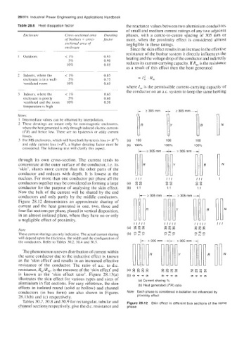
Figure 28.12 demonstrates an approximate sharing of
current and the heat generated in one, two, three and 11.
four flat sections per phase, placed in vertical disposition,
in an almost isolated plane, where they have no or only
a negligible effect of proximity. ftt
ttttt
(a) 8 : ttttt ttttt
mcom
8
mmm
Note mcum mcum
These current sharings are only indicative. The actual current sharing (b) P 2 $2 mc9m mc9m
-r.-
-r.-
will depend upon the thickness, the width and the configuration of t 305 rnrn 4
the conductors. Refer to Tables 30.2, 30.4 and 30.5. t 305 rnm
The phenomenon uneven distribution of current within
the same conductor due to the inductive effect is known N
as the ‘skin effect’ and results in an increased effective
resistance of the conductor. The ratio of a.c. to d.c.
resistance, Rac/Rdc, is the measure of the ‘skin effect’ and (a) g % % g 0000 0000 ~ m
m
mcucum
~
is known as the ‘skin effect ratio’. Figure 28.13(a) (b) m e b m mbbm mbbm
illustrates the skin effect for various types and sizes of (a) Current sharing %
aluminium in flat sections. For easy reference, the skin (b) Heat generated (I‘R) ratio
effects in isolated round (solid or hollow) and channel
conductors (in box form) are also shown in Figures Note Each phase is considered in isolation not influenced by
28.13(b) and (c) respectively. proximity effect
Tables 30.7,30.8 and 30.9 for rectangular, tubular and Figure 28.12 Skin effect in different bus sections of the same
channel sections respectively, give the d.c. resistance and phase