
Page 923 - Industrial Power Engineering and Applications Handbook
P. 923
Carrying power through metal-enclosed bus systems 281873
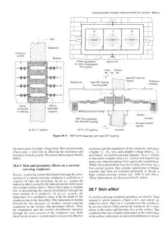
Phase segregation Section XX'
(In case of segregated
*
bus system)
Indoor
Outdoor
1X - I Seal-OFF bushing
Inspection
Sloping top7 Seal-OFF bushing
I mounting plate chamber
Wall frame assembly Insulator
with seal-OFF bushing
Silicagel breather
(a) For LT systems (b) For HT systems Elevation
Figure 28.11 Wall frame assembly with seal-OFF bushing
the main cause of a high voltage drop. Skin and proximity resistance and the impedance of the conductor, and cause
effects play a vital role in affecting the resistance and a higher lic . R,, loss, and a higher voltage drop I,, . Z.
reactance of such systems. We discuss these aspects briefly and reduce its current-carrying capacity. An a.c. system
below. is thus more complex than a d.c. system and requires far
more care when designing it for a particular requirement.
28.6.3 Skin and proximity effects on a current- While these phenomena may be of little relevance for a
carrying conductor low-current system, they assume significance at higher
currents and form an essential parameter to design a
In a d.c. system the current distribution through the cross- high current-carrying system say, 1600 A and above.
section of a current-carrying conductor is uniform as it These phenomena are discussed briefly below.
consists of only the resistance. In an a.c. system the
inductive effect caused by the induced-electric field causes
skin and proximity effects. These effects play a complex
role in determining the current distribution through the 28.7 Skin effect
cross-section of a conductor. In an a.c. system, the
inductance of- a conductor varies with the depth of the A current-carrying conductor produces an electric field
conductor due to the skin effect. This inductance is further around it which induces a back e.m.f. and causes an
affected by the presence of another current-carrying inductive effect. This e.m.f. is produced in the conductor
conductor in the vicinity (the proximity effect). Thus, by its own electric field cutting the conductor. It i\ more
the impedance and the current distribution (density) dense at the centre and becomes less at the surface. The
through the cross-section of the conductor vary. Both conductor thus has a higher inductance at the centre than
these factors on an ax. system tend to increase the effective at the surface, and causes an uneven distribution of current